You are using an out of date browser. It may not display this or other websites correctly.
You should upgrade or use an alternative browser.
You should upgrade or use an alternative browser.
I need help understanding AC electricity and generators (1/3 phase)
- Thread starter fatjay
- Start date
- Views: 12599
More options
Who Replied?
/ I need help understanding AC electricity and generators (1/3 phase)
#41

MossRoad
Super Moderator
- Joined
- Aug 31, 2001
- Messages
- 66,153
- Location
- South Bend, Indiana (near)
- Tractor
- Power Trac PT425 2001 Model Year
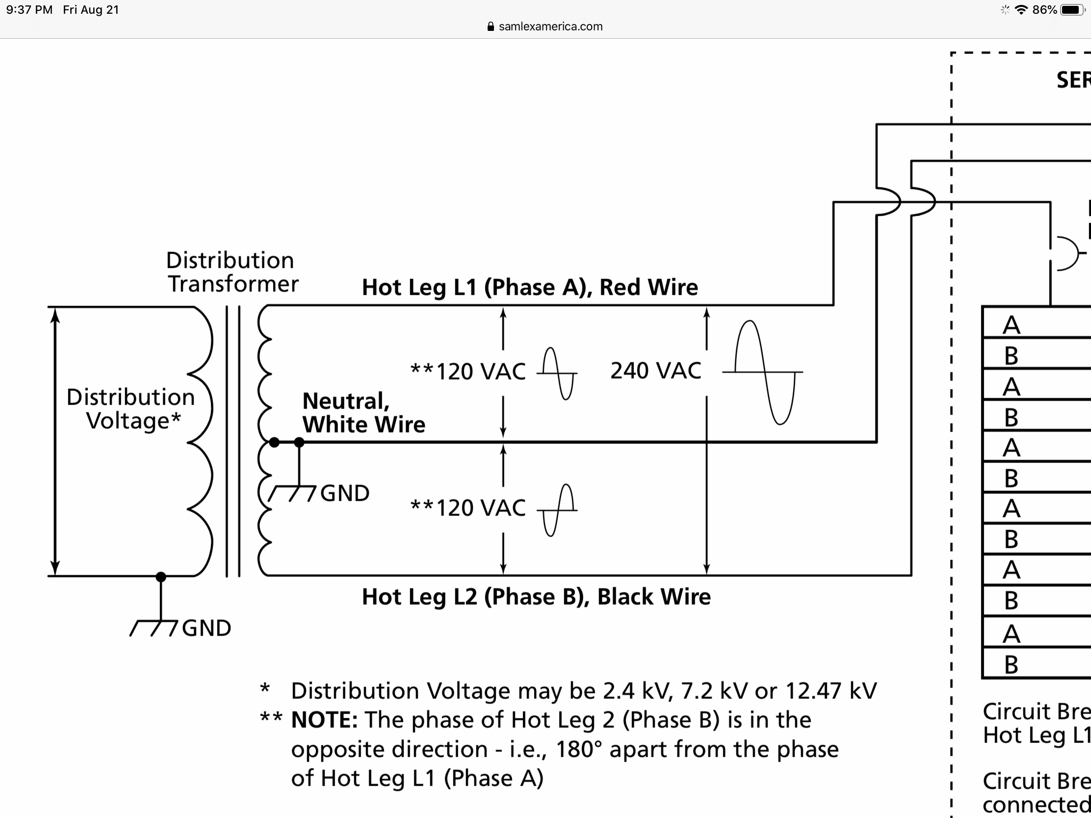
It's a single split phase system.
One 240V phase, that is split into two 120V phases, that are 180 degrees out of phase.
From here:
https://www.samlexamerica.com/suppo...ingleSplitPhaseandMultiWireBranchCircuits.pdf
One 240V phase, that is split into two 120V phases, that are 180 degrees out of phase.
From here:
https://www.samlexamerica.com/suppo...ingleSplitPhaseandMultiWireBranchCircuits.pdf
Attachments

MossRoad
Super Moderator
- Joined
- Aug 31, 2001
- Messages
- 66,153
- Location
- South Bend, Indiana (near)
- Tractor
- Power Trac PT425 2001 Model Year
I beg to differ on the 120/240 being out of phase. AGAIN, someone confuses the issue. If they were 180 degrees out of phase, they would cancel each other out. They are simply different taps, or windings, on a single phase.
Or am I totally misinformed? I'm not an electrical engineer and this stuff, the math, has never been my strong point.
Single phase IS single phase. Not suddently two phases! Not on a generator and not in your house panel.
Look at the sine wave coming out of the top of the center transformer. It's rising.
Look at the sine wave coming out of the bottom of the center transformer. It's falling.
They rise and fall towards and away from each other at the same speed.
So when the top one peaks at +120, the bottom one valleys at -120.
That's how you get your 240V difference.
If the 120v legs were in phase, they'd be rising and falling at the same time. They'd never be 240v apart. They'd be overlapping legs.
They are 180 degrees out of phase to each other.
")
MossRoad
Super Moderator
- Joined
- Aug 31, 2001
- Messages
- 66,153
- Location
- South Bend, Indiana (near)
- Tractor
- Power Trac PT425 2001 Model Year
Does any of that help?
strantor
Platinum Member
So you continue to refuse to answer the question?
CalG
Super Member
- Joined
- Sep 29, 2011
- Messages
- 9,211
- Location
- vermont
- Tractor
- Hurlimann 435, Fordson E27n, Bolens HT-23, Kubota B7200, Kubota B2601
I'm not sure this will help, but...
Grab a clean sheet of paper and arrange it horizontally on your desk before you.
With a bold writing tool, draw a horizontal line midway up the sheet On the left most end of the line , label the line ZERO.
. On the RIGHT end of the horizontal zero line put a horizontal arrow pointing right and the word "time".
About 1 1/2 inches in from the left side of the sheet, draw a bold vertical line. Put a big "Volt" label somewhere above the "zero" label
At the top part of the vertical line put a +V label. at the bottom of the Vertical line put a -V label.
There, you have established a graph space.
Now, at the "origin" or the zero crossing of the Volt and the "time" lines on the left side of the page, midway up. produce a sine curve that goes from the origin, up towards the top of the page, peaks, and then returns to the ZERO time line but does not cross below. Draw one full sine wave cycle. More if you like. where the sine wave contacts the horizontal zero time line the second time, write a small 60hz at the tangent point.
Now grab a different color writing tool.
Again start drawing a sine wave that originates at the intersection of the horizontal and vertical lines. The line proceeds UP and to the right to the same maximum extent as the first sine wave, but in 1/2 the distance to the right (time) and then descends THROUGH the zero line an equal AMPLITUDE below the zero line as it had been ABOVE the zero line only moments before. Turn this new sine wave back up to meet the zero time line at the same point as the first sine wave contacts the zero line.
Clear as mud ;-) But the exercise is worth doing.
Details to note.
120V single phase does NOT CROSS the zero voltage ground. (and it does not matter if you had made the first sine wave below the horizontal zero line)
The Frequency of the applied Voltage is 60 times per second (50 if in the UK etc) That is, the A/C voltage rises from zero to a maximum and back to zero in one cycle.
The actual AMPLITUDE ( maximum voltage) does not effect wave form or cycle time. If viewed on an o-scope, Both 240 and 120 wave forms could be made to appear identical with a tweak of a pair of adjustment knobs. In fact, under heavy service load, both 120 and 240 Volt supplies will SAG, that is the voltage will "droop" to a less than peak value.
240 V single phase CROSSES the zero voltage line with TWICE the total AMPLITUDE of the sine wave in exactly the same time. 1/60 th of a second. Half that time the voltage will be one sign (+) relative to ground, and the other half the time the voltage will be the opposite sign. (-) The PEak Voltage for 240V systems is measured "leg to leg". No ground required!
One Cycle for both 120 and 240 single phase is the time (horizontal distance on the graph you made) And that is constant for both. Entirely based on engine speed for an IC engine powered generator. (Inverter units are MAGIC)
strantor
Platinum Member
Clear as mud ;-) But the exercise is worth doing.
I know what exercise is worth doing... a video of an oscilloscope measuring 480/3ph and compare/contrast with 240 split phase. I'll make the video tomorrow and post it here even if I'm wrong.
MossRoad
Super Moderator
- Joined
- Aug 31, 2001
- Messages
- 66,153
- Location
- South Bend, Indiana (near)
- Tractor
- Power Trac PT425 2001 Model Year
I know what exercise is worth doing... a video of an oscilloscope measuring 480/3ph and compare/contrast with 240 split phase. I'll make the video tomorrow and post it here even if I'm wrong.
Think about it...
Out of phase:
If L1 is going up while L2 is going down. When they reach +120 and -120, they are 240 apart.
In phase:
If L1 is going up while L2 is going up, L1 would reach +120 when L2 hit 0 and L2 would hit -120 when L1 hit 0. They could never get 240 apart if they were in phase.
Make sense?
CalG
Super Member
- Joined
- Sep 29, 2011
- Messages
- 9,211
- Location
- vermont
- Tractor
- Hurlimann 435, Fordson E27n, Bolens HT-23, Kubota B7200, Kubota B2601
I know what exercise is worth doing... a video of an oscilloscope measuring 480/3ph and compare/contrast with 240 split phase. I'll make the video tomorrow and post it here even if I'm wrong.
Great!
Please show the variation between any leg to ground/neutral, and Leg to Leg.
It is always a difficulty to visualize that 120 degrees phase difference between legs 3 phase BECOMES 180 phase difference between any TWO legs.
Magic again... ;-)
LouNY
Super Star Member
- Joined
- Jul 4, 2015
- Messages
- 14,418
- Location
- Greenwich, NY
- Tractor
- Branson 8050, IH 574, Oliver 1550 Diesel Utility (traded in on Branson) NH 8160. Kioti CK2620SECH
If 480 3 ph behaved similar to 120/240 it would be 240/480 and it is not, it is 480 any phase to phase but 277 to ground or 277/480.
strantor
Platinum Member
Not trying to insult anyone so please don't interpret anything I've said in a negative way. You have a nice shop and are a very talented individual.
Here is a DC model. Voltage inversion of the outputs is a known characteristic of center tap transformers and one can't rewrite the laws of physics. Better to look up how they operate than for me to explain.

Here is a DC model. Voltage inversion of the outputs is a known characteristic of center tap transformers and one can't rewrite the laws of physics. Better to look up how they operate than for me to explain.

Grumpycat
Super Member
You are playing fast and free with "ground" which is actually neutral.
If you measure L1 to N on one scope channel and N to L2 on the other, of course it will appear both are in phase. This isn't valid because you are measuring from two different references.
Your battery analogy is incorrect because both batteries are always positive on their positive terminal. L1 is negative when L2 is positive. L1 and L2 always have N in the middle. You can not parallel L1 and L2, they are hard wired in series.
Your CRT scope has channel "add" functions to add or subtract Channel 1 from Channel 2 specifically so one can connect 1 to L1 and 2 to L2 to see the combined signal while each channel's ground is connected to neutral.
Don't confuse ground with neutral. For safety they are kept close but they are not equal.
Your transformers have phase dots specifically because the phases are 180° apart.
L1 to L2 is a single in-sync phase.
L1 to N and L2 to N are 180° out of phase.
L1 to N and N to L2 are in phase but separated by 170 volts.
strantor
Platinum Member
Thank you for the compliment. I admit I have a bit of a chip on my shoulder about this topic and I probably took your comments and others more as a personal attack than what was intended. So far in this thread I have been replying not only to individuals (as they deserve) but to everyone who has ever opposed me on this topic, with unearned ire. I apologize for that and will try to do better.Not trying to insult anyone so please don't interpret anything I've said in a negative way. You have a nice shop and are a very talented individual.
Here is a DC model. Voltage inversion of the outputs is a known characteristic of center tap transformers and one can't rewrite the laws of physics. Better to look up how they operate than for me to explain.
View attachment 667156
For your DC examples I would question the assertion that the batteries flip position, and instead suggest that they flip polarity (in unison) - for an AC equivalent.
strantor
Platinum Member
I'm going to chop up and rearrange your quote in a way that is easier to reply to. But first, I want to say thanks for hearing me out. I can tell by your reply that you watched the whole video, which is more acknowledgement than I expected.
Fair enough, hit taken. In 26 minutes I surely had time to discuss the difference between ground and neutral. If I'd had a cord with neutral I would have been forced to. But this was my welder extension cord, and the green conductor is ground, not neutral. As you know, it's connected to the same point in the panel as neutral, so for the purposes of the video it seemed as well to just standardize on calling it ground as it would not have any bearing on the experiments at hand.
I thought I did a pretty good job of proving that the battery analogy is correct, by actually performing the DC experiments (on video), followed up by performing all the exact same experiments with AC (on video) and demonstrating that the results are precisely equivalent.
As you said, they are hard wired in series. The same current is flowing from one end to the other. The only thing that's reversed is your measurement, because you are measuring from the center tap of the transformer. you're measuring forward from center tap to L2, and you're measuring backward from center tap to L1. Your backward measurement yields an apparent phase reversal.
What do you see?
Surprised?
"This can't be right? what's wrong with my scope?"
Ok, now hit the "invert" button for CH1. This corrects the apparently reversed polarity wave you're seeing on CH1, and now your ADD function changes from a straight line at 0V into a waveform of 240V.
"L1 to L2 is a single in-sync phase." -correct
"L1 to N and L2 to N are 180ー out of phase." - L1 to N and L2 to N yield 180ー out of phase waveforms on an oscilloscope. This does not mean that they are 180 degrees out of phase.
"L1 to N and N to L2 are in phase but separated by 170 volts." - correct.
Try this thought experiment:
If the residential mains were grounded at L1 instead of at the center tap, what would that look like?
(disregard the topic of neutral for a minute and assume no connected loads)
Gnd (L1) to center tap would be 120V
Gnd (L1) to L2 would be 240V.
Gnd (L1) to center tap would be in phase with Gnd (L1) to L2
Center tap to L2 would be in phase with Gnd (L1) to L2
All would be in phase.
Because all ARE in phase.
Changing the grounding point does not reverse polarity of the half the transformer.
In a center-tap-grounded circuit, the only reason that measurements of GND to L1 appear to be reversed polarity with respect to GND to L2, is because the measurement device is connected in reversed polarity with respect to the measurement taken from GND to L2. It is a measurement error, not an actual phase reversal. If it were an actual phase reversal (which is impossible because as you said "L1 and L2, they are hard wired in series"), then L1 - L2 would equal 0V, as I proved in my video.
You are playing fast and free with "ground" which is actually neutral.
Don't confuse ground with neutral. For safety they are kept close but they are not equal.
Fair enough, hit taken. In 26 minutes I surely had time to discuss the difference between ground and neutral. If I'd had a cord with neutral I would have been forced to. But this was my welder extension cord, and the green conductor is ground, not neutral. As you know, it's connected to the same point in the panel as neutral, so for the purposes of the video it seemed as well to just standardize on calling it ground as it would not have any bearing on the experiments at hand.
So any measurement referenced from a point other than ground, is invalid? If that's the case then any measurement of 240V is invalid. It is not possible to measure 240V from ground.If you measure L1 to N on one scope channel and N to L2 on the other, of course it will appear both are in phase. This isn't valid because you are measuring from two different references.
Your battery analogy is incorrect because both batteries are always positive on their positive terminal. L1 is negative when L2 is positive. L1 and L2 always have N in the middle. You can not parallel L1 and L2, they are hard wired in series.
I thought I did a pretty good job of proving that the battery analogy is correct, by actually performing the DC experiments (on video), followed up by performing all the exact same experiments with AC (on video) and demonstrating that the results are precisely equivalent.
As you said, they are hard wired in series. The same current is flowing from one end to the other. The only thing that's reversed is your measurement, because you are measuring from the center tap of the transformer. you're measuring forward from center tap to L2, and you're measuring backward from center tap to L1. Your backward measurement yields an apparent phase reversal.
Correct. do you have a ground-referenced/non-isolated scope? If so, I would encourage you to connect it mains, put probes on L1 and L2, observe your "180 degress out of phase" waveforms, and hit that "add" button.Your CRT scope has channel "add" functions to add or subtract Channel 1 from Channel 2 specifically so one can connect 1 to L1 and 2 to L2 to see the combined signal while each channel's ground is connected to neutral.
What do you see?
Surprised?
"This can't be right? what's wrong with my scope?"
Ok, now hit the "invert" button for CH1. This corrects the apparently reversed polarity wave you're seeing on CH1, and now your ADD function changes from a straight line at 0V into a waveform of 240V.
Your transformers have phase dots specifically because the phases are 180ー apart.
L1 to L2 is a single in-sync phase.
L1 to N and L2 to N are 180ー out of phase.
L1 to N and N to L2 are in phase but separated by 170 volts.
"L1 to L2 is a single in-sync phase." -correct
"L1 to N and L2 to N are 180ー out of phase." - L1 to N and L2 to N yield 180ー out of phase waveforms on an oscilloscope. This does not mean that they are 180 degrees out of phase.
"L1 to N and N to L2 are in phase but separated by 170 volts." - correct.
Try this thought experiment:
If the residential mains were grounded at L1 instead of at the center tap, what would that look like?
(disregard the topic of neutral for a minute and assume no connected loads)
Gnd (L1) to center tap would be 120V
Gnd (L1) to L2 would be 240V.
Gnd (L1) to center tap would be in phase with Gnd (L1) to L2
Center tap to L2 would be in phase with Gnd (L1) to L2
All would be in phase.
Because all ARE in phase.
Changing the grounding point does not reverse polarity of the half the transformer.
In a center-tap-grounded circuit, the only reason that measurements of GND to L1 appear to be reversed polarity with respect to GND to L2, is because the measurement device is connected in reversed polarity with respect to the measurement taken from GND to L2. It is a measurement error, not an actual phase reversal. If it were an actual phase reversal (which is impossible because as you said "L1 and L2, they are hard wired in series"), then L1 - L2 would equal 0V, as I proved in my video.
Last edited:
MossRoad
Super Moderator
- Joined
- Aug 31, 2001
- Messages
- 66,153
- Location
- South Bend, Indiana (near)
- Tractor
- Power Trac PT425 2001 Model Year
MossRoad
Super Moderator
- Joined
- Aug 31, 2001
- Messages
- 66,153
- Location
- South Bend, Indiana (near)
- Tractor
- Power Trac PT425 2001 Model Year
strantor
Platinum Member
Thanks for bringing that to my attention. I'll go fix it.
