You are using an out of date browser. It may not display this or other websites correctly.
You should upgrade or use an alternative browser.
You should upgrade or use an alternative browser.
I need help understanding AC electricity and generators (1/3 phase)
- Thread starter fatjay
- Start date
- Views: 12428
More options
Who Replied?
/ I need help understanding AC electricity and generators (1/3 phase)
#51
Not trying to insult anyone so please don't interpret anything I've said in a negative way. You have a nice shop and are a very talented individual.
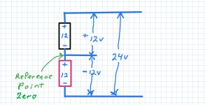
Here is a DC model. Voltage inversion of the outputs is a known characteristic of center tap transformers and one can't rewrite the laws of physics. Better to look up how they operate than for me to explain.

Here is a DC model. Voltage inversion of the outputs is a known characteristic of center tap transformers and one can't rewrite the laws of physics. Better to look up how they operate than for me to explain.

Grumpycat
Super Member
You are playing fast and free with "ground" which is actually neutral.
If you measure L1 to N on one scope channel and N to L2 on the other, of course it will appear both are in phase. This isn't valid because you are measuring from two different references.
Your battery analogy is incorrect because both batteries are always positive on their positive terminal. L1 is negative when L2 is positive. L1 and L2 always have N in the middle. You can not parallel L1 and L2, they are hard wired in series.
Your CRT scope has channel "add" functions to add or subtract Channel 1 from Channel 2 specifically so one can connect 1 to L1 and 2 to L2 to see the combined signal while each channel's ground is connected to neutral.
Don't confuse ground with neutral. For safety they are kept close but they are not equal.
Your transformers have phase dots specifically because the phases are 180° apart.
L1 to L2 is a single in-sync phase.
L1 to N and L2 to N are 180° out of phase.
L1 to N and N to L2 are in phase but separated by 170 volts.
strantor
Platinum Member
Thank you for the compliment. I admit I have a bit of a chip on my shoulder about this topic and I probably took your comments and others more as a personal attack than what was intended. So far in this thread I have been replying not only to individuals (as they deserve) but to everyone who has ever opposed me on this topic, with unearned ire. I apologize for that and will try to do better.Not trying to insult anyone so please don't interpret anything I've said in a negative way. You have a nice shop and are a very talented individual.
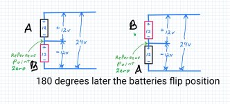
Here is a DC model. Voltage inversion of the outputs is a known characteristic of center tap transformers and one can't rewrite the laws of physics. Better to look up how they operate than for me to explain.
View attachment 667156
For your DC examples I would question the assertion that the batteries flip position, and instead suggest that they flip polarity (in unison) - for an AC equivalent.
strantor
Platinum Member
I'm going to chop up and rearrange your quote in a way that is easier to reply to. But first, I want to say thanks for hearing me out. I can tell by your reply that you watched the whole video, which is more acknowledgement than I expected.
Fair enough, hit taken. In 26 minutes I surely had time to discuss the difference between ground and neutral. If I'd had a cord with neutral I would have been forced to. But this was my welder extension cord, and the green conductor is ground, not neutral. As you know, it's connected to the same point in the panel as neutral, so for the purposes of the video it seemed as well to just standardize on calling it ground as it would not have any bearing on the experiments at hand.
I thought I did a pretty good job of proving that the battery analogy is correct, by actually performing the DC experiments (on video), followed up by performing all the exact same experiments with AC (on video) and demonstrating that the results are precisely equivalent.
As you said, they are hard wired in series. The same current is flowing from one end to the other. The only thing that's reversed is your measurement, because you are measuring from the center tap of the transformer. you're measuring forward from center tap to L2, and you're measuring backward from center tap to L1. Your backward measurement yields an apparent phase reversal.
What do you see?
Surprised?
"This can't be right? what's wrong with my scope?"
Ok, now hit the "invert" button for CH1. This corrects the apparently reversed polarity wave you're seeing on CH1, and now your ADD function changes from a straight line at 0V into a waveform of 240V.
"L1 to L2 is a single in-sync phase." -correct
"L1 to N and L2 to N are 180ー out of phase." - L1 to N and L2 to N yield 180ー out of phase waveforms on an oscilloscope. This does not mean that they are 180 degrees out of phase.
"L1 to N and N to L2 are in phase but separated by 170 volts." - correct.
Try this thought experiment:
If the residential mains were grounded at L1 instead of at the center tap, what would that look like?
(disregard the topic of neutral for a minute and assume no connected loads)
Gnd (L1) to center tap would be 120V
Gnd (L1) to L2 would be 240V.
Gnd (L1) to center tap would be in phase with Gnd (L1) to L2
Center tap to L2 would be in phase with Gnd (L1) to L2
All would be in phase.
Because all ARE in phase.
Changing the grounding point does not reverse polarity of the half the transformer.
In a center-tap-grounded circuit, the only reason that measurements of GND to L1 appear to be reversed polarity with respect to GND to L2, is because the measurement device is connected in reversed polarity with respect to the measurement taken from GND to L2. It is a measurement error, not an actual phase reversal. If it were an actual phase reversal (which is impossible because as you said "L1 and L2, they are hard wired in series"), then L1 - L2 would equal 0V, as I proved in my video.
You are playing fast and free with "ground" which is actually neutral.
Don't confuse ground with neutral. For safety they are kept close but they are not equal.
Fair enough, hit taken. In 26 minutes I surely had time to discuss the difference between ground and neutral. If I'd had a cord with neutral I would have been forced to. But this was my welder extension cord, and the green conductor is ground, not neutral. As you know, it's connected to the same point in the panel as neutral, so for the purposes of the video it seemed as well to just standardize on calling it ground as it would not have any bearing on the experiments at hand.
So any measurement referenced from a point other than ground, is invalid? If that's the case then any measurement of 240V is invalid. It is not possible to measure 240V from ground.If you measure L1 to N on one scope channel and N to L2 on the other, of course it will appear both are in phase. This isn't valid because you are measuring from two different references.
Your battery analogy is incorrect because both batteries are always positive on their positive terminal. L1 is negative when L2 is positive. L1 and L2 always have N in the middle. You can not parallel L1 and L2, they are hard wired in series.
I thought I did a pretty good job of proving that the battery analogy is correct, by actually performing the DC experiments (on video), followed up by performing all the exact same experiments with AC (on video) and demonstrating that the results are precisely equivalent.
As you said, they are hard wired in series. The same current is flowing from one end to the other. The only thing that's reversed is your measurement, because you are measuring from the center tap of the transformer. you're measuring forward from center tap to L2, and you're measuring backward from center tap to L1. Your backward measurement yields an apparent phase reversal.
Correct. do you have a ground-referenced/non-isolated scope? If so, I would encourage you to connect it mains, put probes on L1 and L2, observe your "180 degress out of phase" waveforms, and hit that "add" button.Your CRT scope has channel "add" functions to add or subtract Channel 1 from Channel 2 specifically so one can connect 1 to L1 and 2 to L2 to see the combined signal while each channel's ground is connected to neutral.
What do you see?
Surprised?
"This can't be right? what's wrong with my scope?"
Ok, now hit the "invert" button for CH1. This corrects the apparently reversed polarity wave you're seeing on CH1, and now your ADD function changes from a straight line at 0V into a waveform of 240V.
Your transformers have phase dots specifically because the phases are 180ー apart.
L1 to L2 is a single in-sync phase.
L1 to N and L2 to N are 180ー out of phase.
L1 to N and N to L2 are in phase but separated by 170 volts.
"L1 to L2 is a single in-sync phase." -correct
"L1 to N and L2 to N are 180ー out of phase." - L1 to N and L2 to N yield 180ー out of phase waveforms on an oscilloscope. This does not mean that they are 180 degrees out of phase.
"L1 to N and N to L2 are in phase but separated by 170 volts." - correct.
Try this thought experiment:
If the residential mains were grounded at L1 instead of at the center tap, what would that look like?
(disregard the topic of neutral for a minute and assume no connected loads)
Gnd (L1) to center tap would be 120V
Gnd (L1) to L2 would be 240V.
Gnd (L1) to center tap would be in phase with Gnd (L1) to L2
Center tap to L2 would be in phase with Gnd (L1) to L2
All would be in phase.
Because all ARE in phase.
Changing the grounding point does not reverse polarity of the half the transformer.
In a center-tap-grounded circuit, the only reason that measurements of GND to L1 appear to be reversed polarity with respect to GND to L2, is because the measurement device is connected in reversed polarity with respect to the measurement taken from GND to L2. It is a measurement error, not an actual phase reversal. If it were an actual phase reversal (which is impossible because as you said "L1 and L2, they are hard wired in series"), then L1 - L2 would equal 0V, as I proved in my video.
Last edited:
- Joined
- Aug 31, 2001
- Messages
- 66,078
- Location
- South Bend, Indiana (near)
- Tractor
- Power Trac PT425 2001 Model Year
- Joined
- Aug 31, 2001
- Messages
- 66,078
- Location
- South Bend, Indiana (near)
- Tractor
- Power Trac PT425 2001 Model Year
strantor
Platinum Member
Thanks for bringing that to my attention. I'll go fix it.

