I am thinking the spool on the valve should be all the way out in the neutral position. If anything is holding it from coming all the way out it will not be in neutral. I may be wrong, any other opinions.
You are using an out of date browser. It may not display this or other websites correctly.
You should upgrade or use an alternative browser.
You should upgrade or use an alternative browser.
Three point valve broken!!!
- Thread starter clemsonfor
- Start date
- Views: 19355
More options
Who Replied?
/ Three point valve broken!!!
#81
duanew1
Silver Member
I am thinking the spool on the valve should be all the way out in the neutral position. If anything is holding it from coming all the way out it will not be in neutral. I may be wrong, any other opinions.
According to the diagrams, with the spool all the way out the valve should be set to drop the 3 point.
Last edited:
Indirocz28
Silver Member
- Joined
- Sep 8, 2018
- Messages
- 182
- Tractor
- Yanmar YM2000BD
My post #64 above links to some photos you can compare to. In particular here are Yanmar's shop-wall posters.
https://www.tractorbynet.com/forums/yanmar/220599-hydraulic-system-diagrams.html#post2522872
Insightful, thank you for those!
Hopefully Carey pops up in here and he can directly get some pictures.
I can take some and post them from my 3110 if that would help you. Just tell me what you need.
I have no idea if they are set up the same or not
I need to see essentially what angle the vertical push lever is in when the control lever is in its 3 separate positions. Down, neutral and full up, I guess probably preferably without the retention spring.
I may have to try to cut my control lever shaft from the little vertical piece and re-weld it at a different angle since mine has been welded on.
Indirocz28
Silver Member
- Joined
- Sep 8, 2018
- Messages
- 182
- Tractor
- Yanmar YM2000BD
According to the diagrams, withe spool all the way out the valve should be set to drop the 3 point.
I agree, with no pressure on the spool pin the 3pt should be down. It raises as the spool pin is pushed inward.
Indirocz28
Silver Member
- Joined
- Sep 8, 2018
- Messages
- 182
- Tractor
- Yanmar YM2000BD
Just hooked up my pressure gauge at the pump outlet.
With idle at 1500rpm, the speed lever on the 3pt control about 1/4 of the way up, holding the control lever all the way back and 3pt all the way up, there was a maximum of 1700psi.
With the idle at 1500rpm, and the speed lever all the way open, handle pulled all the way back, 3pt all the way up a maximum of 1000-1200psi.
According to the diagrams, withe spool all the way out the valve should be set to drop the 3 point.
My bad, you are correct. :confused3: Wonder if removing the feedback lever and just manually push you would be able to find the neutral position. As I understand it the spring inside the valve pushes the spool out at all times.
Indirocz28
Silver Member
- Joined
- Sep 8, 2018
- Messages
- 182
- Tractor
- Yanmar YM2000BD
My bad, you are correct. :confused3: Wonder if removing the feedback lever and just manually push you would be able to find the neutral position. As I understand it the spring inside the valve pushes the spool out at all times.
So last night I disconnected the tension spring on the outside, and tried holding the lever gently to see if I could find the neutral. I was unable to find it that way.
This photo from another thread shows the handle all the way forward, the linkage maxed out on the stop nuts, and the 3pt arms down, with the vertical arm that pushes the spool pin almost in a 0* position.
On my tractor, with the 3pt down, the feedback linkage slider (little collar that slides on the feedback rod) is down near the 2d/3rd pinhole on the feedback rod.
When I pick it up, the collar slides forward toward the stop nuts.

OP
clemsonfor
Super Member
So last night I disconnected the tension spring on the outside, and tried holding the lever gently to see if I could find the neutral. I was unable to find it that way.
This photo from another thread shows the handle all the way forward, the linkage maxed out on the stop nuts, and the 3pt arms down, with the vertical arm that pushes the spool pin almost in a 0* position.
On my tractor, with the 3pt down, the feedback linkage slider (little collar that slides on the feedback rod) is down near the 2d/3rd pinhole on the feedback rod.
When I pick it up, the collar slides forward toward the stop nuts.
View attachment 577021
I know for certain my nuts are not that far back on the feedback rod, but I don't think that mag be critical here since I'm sure the one in the picture works as well.
OP
clemsonfor
Super Member


 [
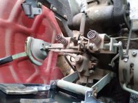
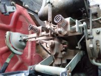
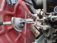
[Ok i went through all the pictures i have posted over the years. All i could see were thumbnail view when i looked through my previous attachments so some may not help but were too small to tell as i selected them. These are pics i posted for other reasons but look to have the linkage in view. These pics are all posted with the lever in the down position and the arms in the down position.
OP
clemsonfor
Super Member
View attachment 577029View attachment 577030View attachment 577031View attachment 577032[
Ok i went through all the pictures i have posted over the years. All i could see were thumbnail view when i looked through my previous attachments so some may not help but were too small to tell as i selected them. These are pics i posted for other reasons but look to have the linkage in view. These pics are all posted with the lever in the down position and the arms in the down position.
well dang, like i said all i could see was thumbnails, so i had no clue what they were till i posted them and clicked a larger view.
The best pics have the rod disconnected from when i removed the arms to replace the o rings behind them!!!
Indirocz28
Silver Member
- Joined
- Sep 8, 2018
- Messages
- 182
- Tractor
- Yanmar YM2000BD
well dang, like i said all i could see was thumbnails, so i had no clue what they were till i posted them and clicked a larger view.
The best pics have the rod disconnected from when i removed the arms to replace the o rings behind them!!!
Haha yep, darnit all! Still, thank you for posting them though.
Indirocz28
Silver Member
- Joined
- Sep 8, 2018
- Messages
- 182
- Tractor
- Yanmar YM2000BD
Even if someone could post a detailed video of their linkage and handle operating to the rise and drop of the 3pt arms that would be helpful as well I think.
OP
clemsonfor
Super Member
Even if someone could post a detailed video of their linkage and handle operating to the rise and drop of the 3pt arms that would be helpful as well I think.
i can easily do that...i just personally cant do it for another 7 or 9 days.
duanew1
Silver Member
Even if someone could post a detailed video of their linkage and handle operating to the rise and drop of the 3pt arms that would be helpful as well I think.
Could you make a video of the area around the valve linkage of the with the camera still and plenty of light. That last picture posted shows me a lot about how the linkage functions.
kenmac
Super Member
- Joined
- Feb 13, 2005
- Messages
- 9,957
- Location
- The Heart of Dixie
- Tractor
- McCormick CX105 Kubota MX 5100 HST,
Indirocz28
Silver Member
- Joined
- Sep 8, 2018
- Messages
- 182
- Tractor
- Yanmar YM2000BD


I think I have figured out the problem.
I think the vertical finger that presses on the spool pin is supposed to rotate freely on the pin that it rides on. Since my finger was broken and welded to the control shaft, I think that is causing it to basically be backwards of what it is supposed to be. For instance, in this picture Clemson posted, and Ken’s nearly identical, thier arms are down, the lever is forward, and the finger is back.
On mine, lever is forward, arms are down, but the finger is forward.
Please excuse the welds and cut, I cut the welds earlier to play with it and tack it back in place in different positions. This is when I came to realize it’s kind of moving backwards.
OP
clemsonfor
Super Member
View attachment 577121
View attachment 577122
I think I have figured out the problem.
I think the vertical finger that presses on the spool pin is supposed to rotate freely on the pin that it rides on. Since my finger was broken and welded to the control shaft, I think that is causing it to basically be backwards of what it is supposed to be. For instance, in this picture Clemson posted, and Ken’s nearly identical, thier arms are down, the lever is forward, and the finger is back.
On mine, lever is forward, arms are down, but the finger is forward.
Please excuse the welds and cut, I cut the welds earlier to play with it and tack it back in place in different positions. This is when I came to realize it’s kind of moving backwards.
I hope your onto something now. Sounds like it broke and someone just Wende it where they thought it should be.
Now sounds like you need to call aaron and see what kind of "fingers" or feedback rods or whatever has been hacked on your tractor, that he has laying around in the parts bins.
kenmac
Super Member
- Joined
- Feb 13, 2005
- Messages
- 9,957
- Location
- The Heart of Dixie
- Tractor
- McCormick CX105 Kubota MX 5100 HST,
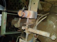
side note if it helps. If I have my lift raised and I remove that spring holding that small vertical block of steel that presses on the valve pin. The lift arms fall.
With your lever all the way back to have the arms raised.The spring must hold that small block against that valve pin (holding it in) for the lift stay raised
With your lever all the way back to have the arms raised.The spring must hold that small block against that valve pin (holding it in) for the lift stay raised
Indirocz28
Silver Member
- Joined
- Sep 8, 2018
- Messages
- 182
- Tractor
- Yanmar YM2000BD
side note if it helps. If I have my lift raised and I remove that spring holding that small vertical block of steel that presses on the valve pin. The lift arms fall.
With your lever all the way back to have the arms raised.The spring must hold that small block against that valve pin (holding it in) for the lift stay raised
I have the spring, it is normally on, but I removed it for fiddling, and didn’t want the finger to break the spot welds and come flying back at me.
kenmac
Super Member
- Joined
- Feb 13, 2005
- Messages
- 9,957
- Location
- The Heart of Dixie
- Tractor
- McCormick CX105 Kubota MX 5100 HST,
with the lever all the way forward ( lift arms down) the bottom of the small steel block that presses on the valve pin, rolls away from the pin, allowing the pin in the valve to come out lowering the arms. It kind of works in a cam action. Hope I'm making sense lol
