Building my bridge crane

   / Building my bridge crane #41  
Yeah I'm going to disagree with you on that! Have you run FEA on both design to look at stress concentrations?

Also bolting is a more controlled solution to splice two beams together. Done all the time in I-beam structures. Multiple bolt holes distribute stress loads and friction force holds everything together.
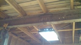
The beauty of bolting is that its something anyone can do. No special tools or skills required. IOW, very little control needed for a serviceable job ... except maybe tighten the bolts again after initial [fast] tensile creep.
 
   / Building my bridge crane #43  
The engineer that helped me with my bridge crane, never once mentioned bolts for splicing my span beam right in the center.:confused:

When it comes to engineering, well I can't even spell engineer!:eek::eek: But I'll side with dragoneggs, I
know what he does for a living!;)
 
   / Building my bridge crane
  • Thread Starter
#44  
got the beam set and welded to trucks. still gotta do the bracing, but it rolls real nice:thumbsup:

IMG_20151124_101911116.jpgIMG_20151124_120832021.jpg

Gee LD, the last I remember, you were sorting through a load of lumber looking for straight purlins. Got to give you a huge attaboy on your awesome shop!

Once we got through the sopping wet spring, it went up pretty quickly.

But I like my work schedule for that. Work 4 12hr days and get 4 off. Can get alot done in 4 full days:thumbsup:
 
   / Building my bridge crane #45  
The engineer that helped me with my bridge crane, never once mentioned bolts for splicing my span beam right in the center.:confused:

When it comes to engineering, well I can't even spell engineer!:eek::eek: But I'll side with dragoneggs, I
know what he does for a living!;)
It is hard to roll a wheel over a bolted splice. Welds work better for that.
 
   / Building my bridge crane #46  
WRONG! ... The tapered ends act to blend the stiffness from the beam into the stiffer area of the patch. Also the taper away from the edges of the flange inhibit a tear/crack beginning at the edge of the flange.

,,, Bolting is a bad idea in comparison to a good weld. Many stress riser sharp edges are inherent in drilling holes, and are difficult to blend out to alleviate cracking. ... Also you lose the strength of the material removed from the holes.
larry

First of all take this info for what you paid for it. Which was nothing. In other words its for discussion only. :rolleyes:

Attached you will find FEA of OPs spliced beam... using tapered and square scab plates. Note hot spots at points of scab plate. With that being said, highest stress is at butt welds between two beams and not at scab plates.

Also I've included approx safety factor at 10,000 lbs with indicated loading... around 1.1. OP should inspect rail at butt weld joint for possible fractures. Proceed at your own risk. Not sure what you are gonna rate this crane at but be careful. Cranes are serious business.

Good day. :cool:

1.jpg2.jpg3.jpg4.jpg5.jpg
 
   / Building my bridge crane #48  
First of all take this info for what you paid for it. Which was nothing.

Attached you will find FEA of OPs spliced beam... using tapered and square scab plates. Note hot spots at points of scab plate. With that being said, highest stress is at butt welds between two beams and not at scab plates.

Good day. :cool:

<img src="http://www.tractorbynet.com/forums/files/build-yourself/448277-building-my-bridge-crane-1-jpg"/><img src="http://www.tractorbynet.com/forums/files/build-yourself/448278-building-my-bridge-crane-2-jpg"/><img src="http://www.tractorbynet.com/forums/files/build-yourself/448279-building-my-bridge-crane-3-jpg"/><img src="http://www.tractorbynet.com/forums/files/build-yourself/448280-building-my-bridge-crane-4-jpg"/><img src="http://www.tractorbynet.com/forums/files/build-yourself/448281-building-my-bridge-crane-5-jpg"/>
Looks like the supports at the end of the beams are restrained supports, not simple supports. Is that the right kind of support for the OP's situation?
 
   / Building my bridge crane #49  
Looks like the supports at the end of the beams are restrained supports, not simple supports. Is that the right kind of support for the OP's situation?
My question too. Might be somewhere between fixed and pinned. For mid beam I would assume pinned to be conservative. Always nice to have FEA tools and thanks for sharing. The devil is in the details as they say...
 
   / Building my bridge crane #50  
I spliced an I beam together in my shop when I removed a wall after I welded it, I used square scabs but plug welded them and welded just the top and bottom.

A little different than the OP's bridge crane though because the top of the beam is attached to the rafters preventing deflection side to side, making it much less likely to fail.
 

Attachments

  • IMG_20151124_170034_688.jpg
    IMG_20151124_170034_688.jpg
    362.5 KB · Views: 360
   / Building my bridge crane #51  
First of all take this info for what you paid for it. Which was nothing. In other words its for discussion only. :rolleyes:

Attached you will find FEA of OPs spliced beam... using tapered and square scab plates. Note hot spots at points of scab plate. With that being said, highest stress is at butt welds between two beams and not at scab plates.

Also I've included approx safety factor at 10,000 lbs with indicated loading... around 1.1. OP should inspect rail at butt weld joint for possible fractures. Proceed at your own risk. Not sure what you are gonna rate this crane at but be careful. Cranes are serious business.

Good day. :cool:

View attachment 448277View attachment 448278View attachment 448279View attachment 448280View attachment 448281
Perhaps you know what that all means; while I have to guess. Aside from WTF on the color code and symbols and other jargon, my guess is that you have made assumptions about scab thickness, taper start point away from the butt weld, and taper angles.

... Why would the butt welds be an issue? The scab plates span them and spare the butt welds from excessive stress by sharing the load.
 
   / Building my bridge crane #52  
I spliced an I beam together in my shop when I removed a wall after I welded it, I used square scabs but plug welded them and welded just the top and bottom.

A little different than the OP's bridge crane though because the top of the beam is attached to the rafters preventing deflection side to side, making it much less likely to fail.
You are talking a torsional issue here. ... A light round tubular member split and welded into the web would make the beam rigid enuf torsionally. -- Not necessary at the 5k max loading LD1 has in mind.
,,,larry
 
   / Building my bridge crane
  • Thread Starter
#53  
Got the first set of braces/gussets up. Probably gonna do 2 more on each side out of square tube going from the truck to the top flange, but a few feet out away from the rail beam. Still have to do the knee braces on the columns yet.

IMG_20151124_175911081.jpgIMG_20151124_175920590.jpgPART_1448407569003_1448407569082.jpg

First of all take this info for what you paid for it. Which was nothing. In other words its for discussion only. :rolleyes:

Attached you will find FEA of OPs spliced beam... using tapered and square scab plates. Note hot spots at points of scab plate. With that being said, highest stress is at butt welds between two beams and not at scab plates.

Also I've included approx safety factor at 10,000 lbs with indicated loading... around 1.1. OP should inspect rail at butt weld joint for possible fractures. Proceed at your own risk. Not sure what you are gonna rate this crane at but be careful. Cranes are serious business.

Good day. :cool:

View attachment 448277View attachment 448278View attachment 448279View attachment 448280View attachment 448281

Not really gonna have a hard and fast rating. Just a personal garage, to lift whatever I have in mind. But figuring on calling it 5k. What do you figure is safe based on what you know?

As to the plates....Never measured the actual thickness with calipers. But Guessing the web plates are either 1/4" or 5/16" and the flange plates are 1/2"
 
   / Building my bridge crane #54  
Looking good LD! I'm getting more jealous each time you post.
 
   / Building my bridge crane #55  
You are talking a torsional issue here. ... A light round tubular member split and welded into the web would make the beam rigid enuf torsionally. -- Not necessary at the 5k max loading LD1 has in mind.
,,,larry

Yes, an I beam will fail much quicker when it is allowed to flex side to side or torsional, like the FEA posted by projectking note the beam buckles not at the joint rather in the center where it is allowed to flex. The addition of a horizontal truss along the top would make it much stronger.

Not unlike the truss on a sheet metal brake.

BPU412-6-HandBrake.jpg


The beam will fail when it lays over a "diamond" at the top of the beam would keep it vertical and make it much stronger, while not inhibiting trolley movement below.

It is simple if you look at it simply, the wider the beam the less likely it is to deflect side to side. Take a yard stick and flex it by both ends it is strong vertically but will flop side to side with little pressure make it a "T" or "H" and the wider you make the horizontal sections, the stronger it gets in that direction.
 
   / Building my bridge crane #56  
Perhaps you know what that all means; while I have to guess. Aside from WTF on the color code and symbols and other jargon, my guess is that you have made assumptions about scab thickness, taper start point away from the butt weld, and taper angles. ... Why would the butt welds be an issue? The scab plates span them and spare the butt welds from excessive stress by sharing the load.

Blue to red is low to high stress.

I used w16 beam same as OP speced. Scab plates are 1/2" thick. Beam ends are beveled for 100% butt weld. Scab plate angles are approximated from pic OP posted.

Even though the beam is welded together and scabbed the joint is still the highest point of stress. Stress will always find weak spot. Similar to nicking a piece of wire and then bending it. It will break at the nick.

The key to reducing stress is having a uniform structural member free of any defects. A continuous I-beam is a perfect example.
 
   / Building my bridge crane #57  
Got the first set of braces/gussets up. Probably gonna do 2 more on each side out of square tube going from the truck to the top flange, but a few feet out away from the rail beam. Still have to do the knee braces on the columns yet. <img src="http://www.tractorbynet.com/forums/files/build-yourself/448302-building-my-bridge-crane-img_20151124_175911081-jpg"/><img src="http://www.tractorbynet.com/forums/files/build-yourself/448303-building-my-bridge-crane-img_20151124_175920590-jpg"/><img src="http://www.tractorbynet.com/forums/files/build-yourself/448304-building-my-bridge-crane-part_1448407569003_1448407569082-jpg"/> Not really gonna have a hard and fast rating. Just a personal garage, to lift whatever I have in mind. But figuring on calling it 5k. What do you figure is safe based on what you know? As to the plates....Never measured the actual thickness with calipers. But Guessing the web plates are either 1/4" or 5/16" and the flange plates are 1/2"

Nice looking work!

I'll decline to say what a rating should be. It depends on entire structure. You probably should load test slightly above your rated weight to make sure everything is okay. 37' span ( I think that's what you said)... Is a pretty big distance with supports only on ends. Some cranes with this kinda span will also use a center runway rail for support. But it all depends on how much load you pick up.

I'm very impressed you are making this bridge crane yourself. Awesome DIY project!!!
 
   / Building my bridge crane #58  
ProjectKing;4298520 [/ATTACH said:


As an engineer, I understand and appreciate the concerns. The OP seems to know more or less what he is doing, and has consulted decent sources, so it appears he is in decent shape, though things like this are always a bit trickier than they may appear to the inexperienced. Shield Arc had the benefit of an engineer that does this stuff daily for his design, and years of, umm, "hobby" welding behind him.

Nonetheless, I think I can appreciate the irony of the somewhat-mutant-fish-shaped Von Mises stress plot on the "fish plate", probably more than most... :D:laughing::shark: Especially since no one else mentioned it...

LD1 - I hope you aren't going to cantilever that hoist out past the ends of the posts by much more than a couple inches....
 
   / Building my bridge crane #59  
ProjectKing,

I have a couple questions on your FEA solution. It looks like you have constrained the ends of the beam in X and Y directions instead of only in Y direction like the OPs crane. The beam won't bend near the end like that in real life. Also it looks like the load is not in the center. Any reason for that? I used to do FEA quite a few years ago. It doesn't look right to me. Just wondering.
 
   / Building my bridge crane
  • Thread Starter
#60  
Blue to red is low to high stress.

I used w16 beam same as OP speced. Scab plates are 1/2" thick. Beam ends are beveled for 100% butt weld. Scab plate angles are approximated from pic OP posted.

Even though the beam is welded together and scabbed the joint is still the highest point of stress. Stress will always find weak spot. Similar to nicking a piece of wire and then bending it. It will break at the nick.

The key to reducing stress is having a uniform structural member free of any defects. A continuous I-beam is a perfect example.

Details are a bit off if you care to run the program again.

ITs not a 16" beam. Its a W18x60. The plates are 5/16" thick for the webs and 1/2" on the flanges. The total beam length is 38', and setting on 6" wide end trucks, the beam over-hangs by about 2" on each one. So the span is basically 36'8" total from truck edge to truck edge.

The trucks are 6x6x1/4" tube and 48" axle to axle.

The gussets connecting beam to truck are 18" high, 18" along the bottom and the same 5/16 plate used to plate the web.

The splice in the beam is not at center. It was a 25' stick and 13' stick welded together.

Trucks are running on 40# rail track, and one side sits on W8x24 beam, the other sits on W8x31 beam. Columns are 118" tall and W10x33 and 15' apart center to center. 12x12x1/2" thick pads on the bottom, held with 4 anchors that are 3/4". Top pad is 1/2" 8x10 welded to the column.

LD1 - I hope you aren't going to cantilever that hoist out past the ends of the posts by much more than a couple inches....

Yes it has the ability to cantilever out about 18-20". Thats beam center can be 18" or so beyond the post. I would have put the post at the end of the rail beam, except my window is in the way. MY calculations show that there is greater stresses and deflection with the trucks right in the middle of the rail beam rather than a little cantilever. And everything checks out okay WITHOUT gussets. Once they go in, there should certainly be no worries.

The knee braces would be something like this
knee braces.jpg
 

Tractor & Equipment Auctions

2023 Kubota BX1880V-1 Sub - Compact Utility Tractor with 54-Inch Mower Deck (A56438)
2023 Kubota...
DRILL CABINET SKID (A58214)
DRILL CABINET SKID...
2023 CASE 580 SUPER N BACKHOE (A60429)
2023 CASE 580...
CAT 930M (A58214)
CAT 930M (A58214)
2020 MACK GRANITE (A58214)
2020 MACK GRANITE...
2016 Deere 180G (A60462)
2016 Deere 180G...
 
Top