Keep um coming. I have read and re-read but I'm still confused.
If I could build this setup with 2x4s and a hammer I would not be such a bother.

I would have had it working months ago.
RonMar, please look at the attached pic and "rub my nose in it"
to see if I can understand.
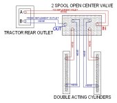
Since the valve states the PBeyond is
optional are you saying I should be able to make things work with 6 hoses?
And not have to run back to the trany??? As Mike mentioned.
Once again I want to thank everyone that is responding to my confusion.
Please keep it coming, I still have not purchased any parts yet and it will be a while before I do.
We are going to my wife's sister's 80th birth day and at the same time her oldest niece who is 60. Let's see if I can still think clearly is that 140 years?