The "thumb"

   / The "thumb" #1  

WinterDeere

Elite Member
Joined
Sep 6, 2011
Messages
3,386
Location
Philadelphia
Tractor
John Deere 3033R; JD 855 MFWD
@Sawyer Rob had posted this in another thread:

It has a thousand uses, I use it all the time, it's been one of my "best buys".

IMG-3576-S.jpg


SR

Serendipitous timing, I was both contemplating a grapple and setting up to modify my own 3-point forks for JDQA loader use. One of my primary loader uses is moving logs, all 15 foot lengths, and I do this using a pair of chain chokers arranged as a sling. It works great, but requires a lot of hopping off the seat, and it's not always the safest operation unhooking the chokers while piling logs.

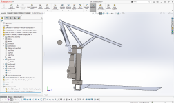
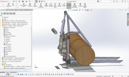
Looking at @Sawyer Rob's rig, I started playing with the idea of using the top link pin on my 3-point fork frame for mounting of a cylinder to control a thumb. I won't need this top link pin when using the forks on the loader, so it's available. It appears all I need is an extra set of tangs welded to the top tube of the fork frame, to let the thumb pivot:
1672456809557.png
(click for full size)

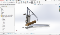
The tube floating in air is the cross-member on the loader frame, need to make sure the cylinder can't collide with that. Shown here with an 18" log, but tested with 6" to 24".

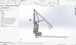
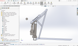
No binding or collisions in full range of travel:
1672456954853.png

1672456981906.png

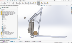
Only potential problem I see, other than needing some more work to pick metal sizing and thicknesses, is that the thumb may tend to lift small logs off the forks due to forming a "V" with the back of the frame at small diameters:
1672457059582.png

I thought I could tune this out with some fiddling of the section lengths on the thumb, but this is the best I've been able to do without either giving up max capacity or causing a potential collision / bending metal between the cylinder and loader cross member or cylinder to thumb spine.

If someone can give me a good guess on square tube size and gauge for that thumb, it might save me some FEA simulation work. The cylinder is only 50mm bore, so around 7850 lb. at my tractor's 2500 psi working pressure. Weight is a concern, as this fork frame already weighs a lot, and I'm often fighting for more loader capacity when moving logs.
 
Last edited:
   / The "thumb"
  • Thread Starter
#2  
Oh, one thing I forgot to ask. Think I need grease-zerk pins in sleeves at the thumb pivots? Got a good source or item recommendation?

I'm not sure how just a plain top link pin would do here, as there won't be a ton of pivoting. But then I think of my bucket curl pins, and the fact that they're greased, and how loose some old loaders still get over time.
 
   / The "thumb" #3  
Yes all rotating/pivoting joints must be grease-able or it’ll wear out in no time.

Your design grometry strikes me as a bit odd. Without setting up a basic dynamics model, my intuitive sense after 20 years as a mechanical engineer is that you are losing a lot of clamping power while simultaneously creating very high stress in the pivot points. Do you have a license for ADAMS?

In my mind the point of a grapple is not to pull material back against the fork uprights- it is to clamp down against the bottom tines, or forks. As in, it’s ok if you can’t fully clamp down tight on one small log and it flops around on your forks, because after all, the load is still contained.

Take a look at this option (probably better to just buy one of these than spend 40 hours doing your own design and fab work)

 
Last edited:
   / The "thumb"
  • Thread Starter
#4  
Thanks, @deezler! Yeah, I don't get to do a lot of mechanical design of implements or dynamic work, just a lot of static models for high power electronics, I'm actually an EE (not ME).
But the add-on thumb grapple is not a good option for lifting long logs, as far as I've seen. I like the forks for this much better, even without a thumb. My thinking was that the addition of the thumb can help hold the log back against the frame/base when I tip the forks forward to retrieve (or even place) one from the top of a pile. Maybe I need to give this more thought, though.

You did misunderstand the complexity involved, as I can whip this job out in closer to 4 hours, not 40! I already have all material in my metal racks, other than the hoses and possibly the greasible pin bushings. I do a decent amount of metal fab, so this simple triangle of square tube and one pair of tangs welded to top of existing frame isn’t a stretch.

No license for ADAMS. I do my modeling in SolidWorks, and simulation in Dassault CST. I believe SolidWorks also has a pretty rudimentary mechanics solver built into it, but since I’m running every day CST for my business, I just go to that for most things.

Did you check @Sawyer Rob's post that I had quoted? That's what I was aiming to roughly mimic, using the fork set I already own. Thinking a single rib on top of that square tube could solve any strength concern, along with reinforcing tabs either side of each tube junction. Possibly teeth on bottom side of tube could replace rib atop, if warranted.
 
Last edited:
   / The "thumb" #5  
I really like SR's set up for moving logs. It will not work for me as I need to be able to pick up load that is 6 ft high once the logs are processed.

Would you show what the arm looks like when the cylinder is retracted? Thanks
 
   / The "thumb" #6  
I would want the grapple curved like mine is, it makes a difference in how you can pick things up.

Picking up a 6' high load is no problem with mine.

And yes, you do want it greaseable, mine is all bushed too.

SR
 
   / The "thumb" #7  
Wow! Solidworks sure has changed since the last time I looked at it. I seem to remember it presenting an almost blank screen for work. 😲
 
   / The "thumb" #8  
I think you are on the path to a good attachment and one worth building. Having a thumb on the backhoe has changed my life... And one for the loader would be nearly as good.

Looking at all the pictures and imagining it in use, I'd rather have a curved thumb. Or better yet, some design with a method of clamping out at the front of the forks as well as back against the SSQA frame.

As it is, it would hold a log nicely and close in allows for the weight of a larger log. But a downside happens when you tilt the forks down and raise the grapple to release the log. Then to dump it, the log has to roll all the way down the forks and jumps off the end unconstrained.
It can really build up some momentum rolling like that.
I'd prefer some way to pick it up out at the end... or at least slow it down when unloading.

But I think it's a project worth doing.
My own first designs are rarely as good as the eventually become. I've learned that there very quickly comes a point in the design process where i just have to build it.
A lot of my initial design geometry is pre-determined by what is available in the scrap iron pile. Buying material is more likely to happen in the re-design.

rScotty
 
   / The "thumb"
  • Thread Starter
#9  
I really like SR's set up for moving logs. It will not work for me as I need to be able to pick up load that is 6 ft high once the logs are processed.
A few of my log piles are at least 6 ft. high, shouldn't be a problem with this rig.

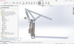
Would you show what the arm looks like when the cylinder is retracted? Thanks
Yep, just like this:

1672497143343.png

I would want the grapple curved like mine is, it makes a difference in how you can pick things up.
Yeah, the inverted "V" created by the forward lower leg and top beam of that triangle was supposed to mimic your curved arm, but without having to actually cut a curve or bend a tube, as that would really increase project complexity with my tools (no plasma cutter). Maybe I could add a short third tube section mitered onto the end of the long arm at 45°, to create that end hook?

Wow! Solidworks sure has changed since the last time I looked at it. I seem to remember it presenting an almost blank screen for work. 😲
I used SolidWorks 2000 and 2003, in those respective years. Then I was away from it until SW 2022, but I don't remember it changing much, other than newer better part mating options. AutoCAD used to present a blank screen, way back in 1980's - early-1990's. Sure you're not thinking of that?
 
Last edited:
   / The "thumb"
  • Thread Starter
#10  
Doh! Yours came in while I was answering the last. Great post, thanks for the pointers. A few quick answers:

A lot of my initial design geometry is pre-determined by what is available in the scrap iron pile. Buying material is more likely to happen in the re-design.

Yes, that's exactly what this is! I chose tubing size, tangs, and cylinder all based on what I had in my inventory. If buying I might have gone with 1-1/2 x 3 inch tubing, rather than 1-1/2" square. But I can always add a 1/4" x 1" or 2" spine atop the arm to add strength in the vertical direction, if needed. If I decide to cut a curve in some 6" x 3/8" flat stock, I could actually put a curved spine (tooth) on the bottom of the thumb.

Looking at all the pictures and imagining it in use, I'd rather have a curved thumb. Or better yet, some design with a method of clamping out at the front of the forks as well as back against the SSQA frame.

Two options:

First, I could quickly and easily add another tube section mitered onto the end:

1672498526757.png
(click for full size)

Second option is more work without a plasma cutter, but I could cut a piece of 6 x 3/8" flat stock I have into a curve, and weld it onto the bottom of the arm. This might be prone to side-bending if it's just a single thickness with much extension from the arm:

1672498932319.png

As it is, it would hold a log nicely and close in allows for the weight of a larger log. But a downside happens when you tilt the forks down and raise the grapple to release the log. Then to dump it, the log has to roll all the way down the forks and jumps off the end unconstrained.
It can really build up some momentum rolling like that.
I thought I'd be able to more slowly release it with the straight arm than the curved, to be honest. Have to think that thru, as one serious shortcoming is the fact that the 3rd function I have available to control this is off a "bang-bang" electric solenoid controlled by thumb switch on my joystick, it's not proportional.

Speaking of which I was planning to add needle valves or restrictor plates to the input ports on the cylinders to be able to adjust thumb speed, unless Deere offers some valve similar to the 3-point float-down valve, to do the same right on the tractor.

I'd prefer some way to pick it up out at the end... or at least slow it down when unloading.

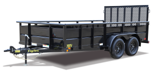
The most frequent use will be lifting logs off a pile and setting them on the ground for bucking, in which case I think I can control the descent by how steeply I angle the forks down. The other potential use would be lifting logs out of a trailer, but I'd need shorter forks to get into the trailer more easily, and I'd have to be careful not to catch the far wall of the trailer with the thumb. It's a closed-side trailer with a railing about 2 feet above the floor:

1672499224861.png

But I think it's a project worth doing.
My own first designs are rarely as good as the eventually become. I've learned that there very quickly comes a point in the design process where i just have to build it.

Thanks! Yes, spent my career as a design engineer, and I'm all too familiar with those caught in analysis paralysis. Get it close, then build it. You'll learn more from rev.A than you think, and quickly mod it or spin rev.B to be much better.
 
Last edited:
 
Top