My Solar Panel Power Project

/ My Solar Panel Power Project #1  

eepete

Platinum Member
Joined
Sep 30, 2009
Messages
963
Location
Efland, NC
Tractor
JD 4520, Kubota B21, JD 318
I decided to put up some solar photovoltaic panels. Here's an overview of the project:

Pete
 
Last edited:
/ My Solar Panel Power Project
  • Thread Starter
#2  
These pictures are shared with my 30 x 40 outbuilding project. The first shot is a before picture. I had a big pile of topsoil. If you look beyond and to the left of that, you will see a drywall bucket on a post. These are pipes that I put in for the solar project back during construction of the house.

The next shot is breaking ground. I had my new box blade on the JD 4520 and cleared the topsoil for the solar array field and inverter shed. You can see the materials for the project off to the right. The Kubota B21 TLB was there for moral support.

The 3rd shot shows the solar area with all its conduit in the ground (as I get ahead of my self a bit). You can see where the Morton Building will go, as well as the driveway into the building.

And finally, here is the Morton Building done. Final landscaping will happen this fall when the weather is better suited for that task.
 

Attachments

  • 1_before.jpg
    1_before.jpg
    511.3 KB · Views: 574
  • 2_solar_topsoil.jpg
    2_solar_topsoil.jpg
    659.5 KB · Views: 550
  • 3_course_grading.jpg
    3_course_grading.jpg
    760 KB · Views: 689
  • 4_ext_pre_final_grade.jpg
    4_ext_pre_final_grade.jpg
    217.1 KB · Views: 859
Last edited:
/ My Solar Panel Power Project
  • Thread Starter
#3  
This shot is the layout for the solar array and outbuilding. I am calling the outbuilding the Inverter Shed because it houses the electronic device that turns the DC into AC which is called an Inverter. The array consists of 36 panels stacked in 9 groups of 4. These are 216 watt panels, for a DC power of 7.77 KW. The two Low Voltage conduit goes to the north side of the inverter shed. There are two more conduits, a 2.5 electrical and a 3 PVC that go to the south side of the inverter shed. These will be used for power and an air line back from an air compressor that will be in the outbuilding feeding the garage so I do not have to listen to the compressor.

There are also two conduits that go south (up in this drawing) under the array. A 2.5 electrical, and a 3 PVC. This gives me a way to get power and other things to whatever the next project is that lies beyond the solar array. There is also a 1.5 conduit that goes to the DC combiner under the solar array. This devices parallels 3 clusters of 12 panels. It has fuses for each cluster and a DC surge protector. At the last moment, I added another 2.5 conduit going west (right) in case some project needed to go that direction some day.

So the inverter shed has 9 conduits coming up into it. The entire array has a circle of #6 copper buried around it as a ground. It comes up into the array on each side to ground the panels. The ground also goes up into the inverter shed at the power company feed (Piedmont Drop) and at the inverter. It also goes up to the combiner to provide ground for the DC protection. There is about 200 of ground wire here, and an additional 100 feet of 1.5 copper strap. This is burred about 3 down.
 

Attachments

  • 5_array_ground_layout.jpg
    5_array_ground_layout.jpg
    251.7 KB · Views: 576
Last edited:
/ My Solar Panel Power Project
  • Thread Starter
#4  
The next shot looks south from what will be the inside of the inverter shed. You can see the trench for future projects in the center. When the sun hit it, I knew I had the whole mess pointing pretty close to due south. You can see the wiggly trench to the DC combiner on the right, and the trench for the power company drop going to the left.

The next shot is this same future use trench after conduit was put in.

The next shot shows a titled view of it all. I know it is a little confusing... You can see the conduit up in the air where the inverter shed will be. You can see the trench for the power company drop to the left. Just beyond that is the trench for ground. You can see the zig zag trench for the DC combiner to the right. Just out of view is where the trench for things that go to the outbuilding will be.

The next shows is a view looking down the utility company drop. The ground trench is just to the left of that. I have not done the trenches to the outbuilding, but they go from the pole on the far right into the inverter shed area.

The final shot shows an opposite view. Here I am aligned with the ground trench. You can see the 1.5 conduit for the DC combiner, and further down the future use conduit. And in the background on the left is that drywall bucket with the conduit from the garage outbuilding. I put that in after all this trenching was filled up.

I wish I could have got an arial shot of all this. It was a fun problem to figure out how to dig all this up and that added some extra challenge to the project. So with all the conduit in place, ground wire, ground strap and ground rods (and the attendant county inspections) it was all covered up. I had reference stakes so I could go back later and drill the holes for the support rod for the solar panel array, and find the ground rods. Drilling into all this had to be pretty accurate given all this buried infrastructure.
 

Attachments

  • 9_trenches_w.jpg
    9_trenches_w.jpg
    732.5 KB · Views: 317
  • 8_trenches_SW.jpg
    8_trenches_SW.jpg
    737.3 KB · Views: 327
  • 7_trenches_looking_north.jpg
    7_trenches_looking_north.jpg
    738.3 KB · Views: 432
  • 6_trenches_looking_south.jpg
    6_trenches_looking_south.jpg
    793.9 KB · Views: 345
  • 10_trenches_east.jpg
    10_trenches_east.jpg
    800 KB · Views: 309
Last edited:
/ My Solar Panel Power Project
  • Thread Starter
#5  
Now it is time to build the inverter shed. Carpentry is not my strong suite, and all I had for tools is a drill and hand skill saw. So I drilled holes with my post hold digger (PHD) and put 12 6x6 for the corners of this 6 foot by 8 foot shed. I put a 4x4 in the middle so I can add a screen door later. I wanted roof overhangs too. It took a come along and a little finesse to get the 2x8 at the top to pull together and get this all square.

Next shot is after the roof was put on. After this, I had to frame in for my funny angled sides.

The next shot is looking into the shed. It is open to the north so the inverter can get lots of air. The shed had a 3/4 pressure treated plywood on the back, and 1/2 PT plywood on the sides. I then used Hardi Panel (cement fiberboard) for the sides. The funny angled sides are so that there are not 90 degree areas where wasps can make their nests. Between that angle and painting it white, no worries about wasps. I had to use Bondo (car repair stuff) to fill in the gaps on the Hardi panel and smooth out the looks of everything.

It took a lot of work to figure out how to cut the Hardi panel to get all those funny corners so they worked out. Later this fall, I will put a screen door on the right and screen on the left. The top will come down about 2 (the inside height is 8 feet and the bottom will also have about 2 of covering. The air compressor for the garage goes to the left.

And yeah, after I got it done I kicked myself for not going 8 x 8. I did it this way so that the roof was 8 deep (6 inside plus a 1 overhang). At any rate, a 6 x 8 building with 6x6 posts 2.5 in the ground should be plenty sturdy. Hardi/cement fiberboard means no worry about boring bees (once the front is on). Eventually, as I do the final landscaping on this and the garage, there will be a gravel boarder around the shed.

The last shot is a side view. The facia is Hardi board. I got 1x4 which forced me to use 1x3 rafters which made the whole framing of the roof funny. I should have got 1x6 board and used all 2 x 4. Oh well, it is hard to argue with something that is done. I would like to argue as to why it is hard to use contractions on this site. It sounds like this was written by Commander Data on Star Trek.
 

Attachments

  • 14_ished_side.jpg
    14_ished_side.jpg
    304.2 KB · Views: 378
  • 13_ished_front.jpg
    13_ished_front.jpg
    352.8 KB · Views: 382
  • 12_ished_roof.jpg
    12_ished_roof.jpg
    661.7 KB · Views: 441
  • 11_ished_frame.jpg
    11_ished_frame.jpg
    528.7 KB · Views: 456
/ My Solar Panel Power Project
  • Thread Starter
#6  
So here is a picture of the roof lines of the place. The inverter shed, outbuilding garage, garage on the house, and the house. Got the angles right, looks like a man built set of mountain peaks...

And here is a picture of the PHD on the tractor because everyone likes tractor pictures :thumbsup:.
 

Attachments

  • 15_rooflines.jpg
    15_rooflines.jpg
    508.1 KB · Views: 574
  • 15a_phd_on_4520.jpg
    15a_phd_on_4520.jpg
    541.3 KB · Views: 448
/ My Solar Panel Power Project
  • Thread Starter
#7  
Now it is time to focus on installing the supports for the panels. The aluminum rails that hold the panels are supported by 3/8 inch stainless steel threaded rod. There are six rods supporting the two rails that hold 4 panels which weight about 50 pounds each. So after a little calculating and measuring, I drilled some 16 foot long 2x4s with the holes where I wanted the rods. It took 12 2x4s to support the 54 rods needed for all this.

After drilling 54 holes with a 6 inch auger where the hole had to be within 3 inches of the right spot, I am starting to get the hang of using a PHD. The next show shows the rods in the holes in with concrete. It took about 2.25 yards to pour fill the holes and put a concrete pad in the inverter shed. I was short about .1 yards. This shot also shows the start of a pea gravel base on landscape cloth. You can see the post for the DC combiner in the middle of the array.

This has not been a cool summer. Here I am half way done with the 1st of 9 sets of rails and panels. If you look at the bottom of the picture, you can see inch tall pieces of 4 inch PVC pipe. These will be filled with concrete once things are set up right. A mistake I made was this: I should have put the PVC sleeves on the front support rods before any panel mounting started. The 2x4 forms had everything lined up right. The weight of all this pushed the rods forward a bit, and tweaking the position of the rails made things worse.
 

Attachments

  • 18_first_pannel_hot.jpg
    18_first_pannel_hot.jpg
    535.8 KB · Views: 587
  • 17_concrete_gravel.jpg
    17_concrete_gravel.jpg
    667.3 KB · Views: 607
  • 16_rod_forms.jpg
    16_rod_forms.jpg
    384.5 KB · Views: 525
Last edited:
/ My Solar Panel Power Project
  • Thread Starter
#8  
Here is the 1st group of panels done.

The next shot shows the whole area covered in gravel, and the brackets that hold the rails up ready to go. I also put neoprene washers on both sides of the angle brackets that hold up the rails. This reduced the contact area of the stainless hardware and the aluminum, and gave the whole system a little more room for metal to expand and contract with temperature.

All the panels are up and the PVC sleeves are filled. The 1st four groups are a little off, the last 5 are better. Seems like you only know how to do something after you are finished.

Here is a closeup of the ground connections. You can see two #6 wires going off to the left. They go up onto the array and ground the panels for both lightning and ground fault safety. You can see where the copper strap connects in. This is the ground wires that were buried back in October some 9 months ago. You can also see a zinc sacrificial anode that is connected to all this so if there are any galvanic corrosion problems, the anode can loose. I later soldered the #6 wires together with tin solder (plumbing solder). So the split lugs give the strength, the solder gives a good connection for even the smallest currents.

The inverter has a GFI for the DC. If there is any leakage between the DC connections and ground, it shuts down the connection to the DC. Between that and the grounding of the array, things should be safer. But the panels have about 400 volts open circuit, that drops down to about 340 under load when the entire array provides about 22 amps. Important safety tip: Do not disconnect any DC leads when the system is under load.
 

Attachments

  • 19_first_array_done.jpg
    19_first_array_done.jpg
    600.5 KB · Views: 375
  • 20_array_area.jpg
    20_array_area.jpg
    642.5 KB · Views: 329
  • 21_array_side_view.jpg
    21_array_side_view.jpg
    563.4 KB · Views: 714
  • 22_array_ground.jpg
    22_array_ground.jpg
    638.1 KB · Views: 439
Last edited:
/ My Solar Panel Power Project
  • Thread Starter
#9  
So here is the entire array done. This winter when it is not Africa Hot out, I will get some buddies and clean up the four on the right. It is about a 2 degree error on some.

I needed to figure out how to series connect the groups of 12 panels so I was not trying to think out in the field. This also let me figure out where to put the DC combiner and what length of leads to order to connect the panels to the combiner. All the lengths are matched so the voltage drop is the same. This is shown in the .pdf file.

The utility company showed up to connect to the commercial mains. I had 120 feet of 2.5 inch conduit buried for them. I did this because it crosses the geothermal heat pump fields, so I had to had dig where the intersection was to be sure I did not hit any buried geothermal line. They should have all been down at 5 feet deep, but there were a few places we hit rock and they came up a bit. I did not find any of the geothermal lines, but if I had not been careful I am sure I would have. The dug in about 50 feet of line. Most of all, it is a picture of another piece of equipment :thumbsup:.

They wired up to the meter base, put in a fancy meter that keeps track of what you push into the grid (where I get paid) and what you take from the grid (where I pay them).
 

Attachments

  • 26_meter_connection.jpg
    26_meter_connection.jpg
    326.5 KB · Views: 919
  • 25_burry_mains_drop.jpg
    25_burry_mains_drop.jpg
    604.2 KB · Views: 397
  • 24_solar_array.pdf
    13.1 KB · Views: 354
  • 23_final_array.jpg
    23_final_array.jpg
    169.9 KB · Views: 623
/ My Solar Panel Power Project
  • Thread Starter
#10  
I turned it all on and it worked :D. It was cloudy and rainy today, so we only put out about 250 Watts of power :(. But that is OK, tomorrow is another day and I will post when I have some real power to brag about. I will also take a shot of the electrical side of it all in the inverter shed.

I've got a little written blurb I am working on that explains a bit about grid tie systems and why I think they are worth the effort. I will be posting that in a few posts in the days ahead.

Pete
 
Last edited:
/ My Solar Panel Power Project
  • Thread Starter
#11  
Here is a shot of the AC wiring in the inverter shed. Nothing fancy. I did put in a light and outlet in case I have to work on anything.

The other shot is the reverse power (power I have fed the grid) as of this morning. 6 KHW, so I've made 90 cents so far today. This is not a get rich quick scheme :laughing:
 

Attachments

  • 27_ished_wiring.jpg
    27_ished_wiring.jpg
    180.4 KB · Views: 361
  • 28_reverse_pwr_meter.jpg
    28_reverse_pwr_meter.jpg
    151.4 KB · Views: 308
/ My Solar Panel Power Project
  • Thread Starter
#12  
Here are three shots from the display on the inverter. You can see the DC volts from the array, the DC amps, and the AC power out in Watts. The inverter claims to be 96% efficient. There is some variance here since these are real time values and the pictures were taken at different times, but it looks close enough for me.

Next step is to work on the wiring and sensors for logging the array power out and the power the house uses. That's going to take a month or so.

Pete
 

Attachments

  • 30_DC_volts.jpg
    30_DC_volts.jpg
    210.3 KB · Views: 248
  • 31_DC_amps.jpg
    31_DC_amps.jpg
    210.2 KB · Views: 265
  • 29_pouwer_out.jpg
    29_pouwer_out.jpg
    186.9 KB · Views: 257
/ My Solar Panel Power Project #13  
Okay very interesting, But how much did it cost and how many years do you expect payback to take.

jake
 
/ My Solar Panel Power Project #14  
Aside from why you did this in the first place - did you look at tracking systems instead of the fixed array and if so what swayed you to the fixed system?
 
/ My Solar Panel Power Project #15  
You sure have been busy Pete. Very nice project. I wondered too about the panel angle, not tracking so much as being able to set a Winter and Summer angle for the collectors.

It's nice you can have your array near the ground, don't need height for snow slide off accumulation in your area I'm thinking. :)

Thanks for sharing.
Dave.
 
/ My Solar Panel Power Project #16  
Very cool. I also am wondering about the cost. I have researched solar several times and always found it to be cost prohibitive.
 
/ My Solar Panel Power Project #17  
Good Write-Up!

Make sure you post the output and how it's working out in the future.

I Like It!
 
/ My Solar Panel Power Project #18  
I've looked into it and the cost just doesn't justify doing it for me. I really do like the idea of not having to pay for power. But Vermont isn't one of the sunny states so that pushes out the ROI time. Does your state have a special price the utility must pay you for the power or do they just give you wholesale price. I don't know for sure but I've been told the new digital meters track both in coming and returning power independently so they know how much you've supplied.
 
/ My Solar Panel Power Project
  • Thread Starter
#19  
Costs:

Cells, rails, hardware: 31,700
10 KW inverter: 5900
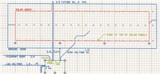
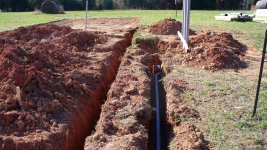
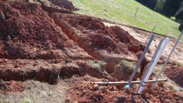
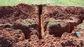
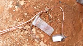
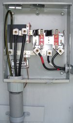
Wire, conduit, panels: 565
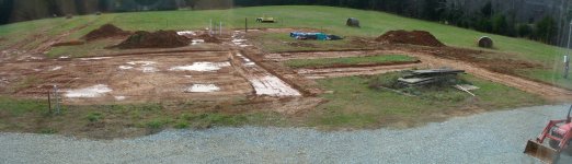
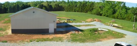
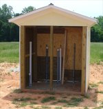
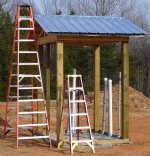
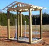
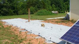
Shed: 1000 (need to go through invoices and get that nailed down better, lots of Lowes trips....
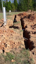
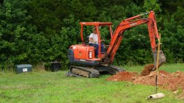
Concrete & labor: 450 (I hired a local group to help with labor- a good idea)

Total: $ 39,615

After Fed and State tax credits, it should be about $20K. I'm not including my labor.

I have a contract to buy $1669 worth of power each year, which in the narrowest sense of "payback" means 12 years. The system has a 20 year life, where that means it outputs 90% of it's original capacity.

Most discussions of payback have subtle biases built in. I'll bet very few tractor owners can come up with a payback time for their equipment. So payback times tend to be things people manipulate to justify what they wanted in the first place. Seems unlikely I'm that objective and an exception to the rule.

Things that modify the payback time are:
Future cost of electricity and if a time of use billing goes into effect.
Cost of lost opportunity of money (think "If I had left that money in a money market or bond fund, would I be better off in 20 years?")
Is your labor really free? Cost of lost opportunity for my time.

So if power cost don't increase, and interest rates or bond rates go back up into the 5-7 percent range, I should have kept my money. If this area went to a 30 cents per KWH time of day use (like some parts of California) and the interest rates and bond rates stay below 2.5%, I look like a genius with a 6 year payback and making about $2700 per year or so.

If you look at this from a strictly economic point of view, you can't justify it. But by the same stringent rules, I couldn't justify my tractors (vs. hiring the big jobs out). At this point in the solar game, people playing have justifications beyond the simple economics.

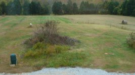
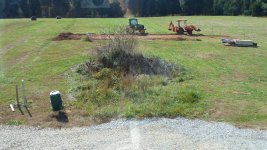
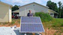
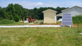
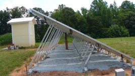
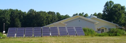
As for the tracking system and panel angle, this fixed array is certainly the simplest thing to do in terms of moving cost and semi-anual maintenance. It is probably representative of what you would see in a residential environment. Which leads me to part of the why:

I was ready to launch a home automation product in 2009 that is best for new residential construction in the 3000 to 6000 sq foot home size. Yeah, I can call them all right :laughing:. But there are lots of people spending $10K to $100K on solar panels. With no new software or sensors, I can monitor all that stuff so they can look at their energy use and generation from the house or office. And then after that there's a "Oh yeah, it also does home automation too" moment. So this will let me learn all about this sort of thing and help me start up a new business.

In my county in NC alone there are 46 small PV installations, and over 330 in the state. Another part of "why" is because it is an interesting project and I enjoyed doing it. Being an early adopter is usually tricky and expensive. I know people who paid $5K in 1985 (or about $15K in todays dollars) to by a IBM PC with a _full_ 620K (or so) so they could type letters and write programs. I spent $2K in 1983 for an 8 Mbyte hard drive for my home computer I built. I spent $2.5K in 1971 for a used PDP-8 computer. All that paid of handsomely as time marched on. If I had waited for computers to become economically viable, the catch up game on the technology would have been too much.

I mentioned at the start of this post about biases, I want mine to be clear and fully admit that on economics alone, solar PV is not there.

I'm going to do about 3 posts next with a thought on solar PV power. A heads up to the monitors of the site, if it's too off topic or deemed political nuke it and there will be no hard feelings. I think there are some interesting aspects to solar PV down the road that are worth thinking about. Lets NOT have a thread about global warming, energy tax subsides, and the like. Those have been beaten to death already. I'm just trying to explain what I did, give some of my thoughts as to why I did it, and then get people to think about what (if any) role solar PV might have for the U.S.

Pete
 
/ My Solar Panel Power Project
  • Thread Starter
#20  
Solar Power thoughts, part 1:
Note: for some reason, single and double quotes get turned into extended character sets when I cut and paste from a document. I have tried to catch all these. Not sure what is going on here...

Solar photovoltaic cells (PV cells) are silicon based devices that can turn sunlight into electricity. The cells are housed in an aluminum frame, backed by plastic, covered by glass. These are called a panel. A typical panel is about 2 feet by 4 feet and weights about 50 pounds.
The panels are specified by what their maximum output power is, in Watts. They output a certain voltage (around 36 to 44 volts) as some current (around 4 to 8 amps). Several panels are wired in series to obtain voltages in the 280 to 450 volts range.

Now lets look at a specific case, a 2 kilowatt (2 KW) system. It might have 10 200 watt panels. Physically, there might be two sets of rails supporting 5 panels each and the entire assembly would weigh about 600 pounds. This could be mounted on a rooftop or on the ground. The mounting system would require 4 or 6 attachment points, depending on location, weather conditions, means of attachment to a roof and the like. The panels have a 20 year life, so if the panels are installed at the same time as a shingle roof, the difficulty accessing the roof should not be an issue- both run out of life about the same time.

So now we have solar panels on the ground or roof, and they will put out about 2KW of direct current (DC) power peak (when the sun is shining bright and high overhead). We want to take this energy and feed it back into the utility grid. So we need a grid tie system. A device called an inverter takes the DC and makes alternating current (AC) at 240 volts (the stuff your house uses). The inverter takes the DC in and makes AC out and in doing so supplies the grid with power. The inverter is on the order of 75 to 95% efficient, we will use a value of 90%. So the 2 KW of DC in will output 1800 watts of AC out. The actual output power can vary from as low as a 100 Watts up to the full 1800 Watts depending on how much sun there is and the angle of the sun.

Now lets think about a 3 ton (or 36,000 BTU) heat pump with a dual speed compressor. At low speed, it runs at about one half the rating and at high speed it runs at rating. This unit will draw about 4 amps or very roughly one kilowatt at the half compressor speed. It will pull about 7.5 amps or about 1800 watts at full power. This size unit is used for houses in the range of 1500 to 2500 square feet, depending on climate, amount of insulation in the house, quality and surface area of windows, house orientation and occupancy load. What is interesting is that this unit can be considered to be the average size in a house.
 

Marketplace Items

2022 Mac Trailers 48ft. T/A Walking Floor Trailer (A64556)
2022 Mac Trailers...
2022 EZ-GO ELITE ELECTRIC GOLF CART (A63276)
2022 EZ-GO ELITE...
2022 EZ-GO ELITE ELECTRIC GOLF CART (A63276)
2022 EZ-GO ELITE...
CLARK FORKLIFT (A63291)
CLARK FORKLIFT...
Wooden chair (A64557)
New/Unused Wolverine 78in Quick Attach Smooth Bucket (A65583)
New/Unused...
 
Top