Oliver1655
Gold Member
- Joined
- Jun 25, 2010
- Messages
- 253
- Tractor
- Oliver 1655
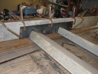
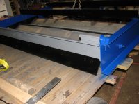
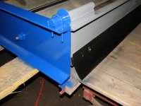
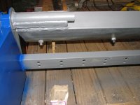
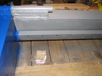
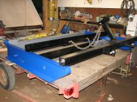
Overall Size is 8 ft 6 inches wide & just under 6 ft long. The cutting edges are 8 ft across. I wasn't sure how much lower the cutting edge should be below the skids so I decided to make the depth adjustable. Then the debate was should the blades be straight across or angled to direct material sideways. In the future I will be building a grader for cutting ditches & crowning so in the end I decided to have the blades straight across. Next decision was whether to have 2 cutting edges at the same height or to have the front one higher or lower than the second. Since the blades will be adjustable pivoting at the rear, they ended up level with the bottom of the skids in the up position. As the blades are lowered in 1/4 in increments, the front blade becomes lower than the secondary cutting edge. I decided to add a hinged drag at the back which can also be used as a back blade.
Let the pictures begin!
Let the pictures begin!
Attachments
-
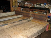 Basic lay out.jpg265 KB · Views: 650
 -
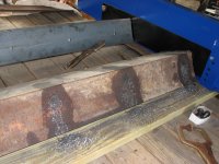
 Marking Skids.jpg90.3 KB · Views: 427
 -
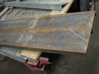
 Skids ready for center section.jpg289.7 KB · Views: 667
 -
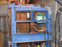 Homemade press - 20 ton jack.jpg339.9 KB · Views: 617
 -
 Clamped to large piece of metal for heat sink.jpg259.2 KB · Views: 557
 -
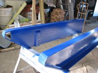
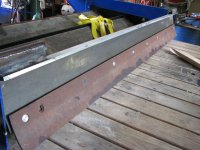
 Installing cutting edges.jpg275 KB · Views: 864
 -
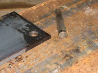 Transfer punch.jpg310.3 KB · Views: 422
 From my experience, it does not seem like it will.