OK, I think we're getting closer - gonna see if I can clear up/re-state a couple things...
First off, I probably shouldn't have referred to "Tank seals" - they are really the seals that keep LOW pressure fluid from finding a "sneak" path out the ends of the valve where the spools move back and forth - And, as mentioned earlier these seals are only intended for lower (under 500 psi typically) pressures, cost being the (probably) main factor.
Please download this
http://www.princehyd.com/portals/0/techFAQ/OpenCenterPbDA.pdf for reference -
So, in a power beyond circuit with
nothing activated (first diagram), you have essentially
no high pressure in the circuit except for unknowns which are
ISOLATED from everything else by spools being in neutral position (no flow to or from any WORK ports)
The pump is moving fluid, and technically NOTHING is at ZERO pressure, because any time you have FLOW you will have pressure DROPS across every resistance, no matter how slight. However, the pressure under these conditions is very low compared to a work port being opened (valve lever being moved)
Under these conditions, NO PART of the valve other than WORK ports (if that) will see high pressure.
Second diagram - One work port actuated, pump develops pressure out the work port and into the cylinder - this diagram ***-U-ME's
full actuation of the valve so
ALL pump flow/pressure is directed to the cylinder - that's why the Power Beyond path is shown in WHITE, with no flow.
Third diagram - This shows using the Tank port of the first valve for Power beyond, conditions being that the SECOND valve is being actuated to drive a cylinder - this puts the FIRST valve's IN and TANK ports both at high pressure - you can see from the little blue "tear drops" WHERE the leakage may happen - here's why...
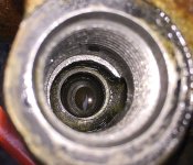
Hydraulic spool valves are made with
REALLY tight tolerances so they don't need INTERNAL O-ring seals - typically less than a thousanth, some only 2-3 TEN thousanths of an inch clearance between the spool and its bore - under typical usage (no power beyond), the relatively low tank gallery pressures can be contained by O-rings at the OUTER ends of the spool pieces, and spent fluid can just take the path of least resistance back to tank -
BUT - if internal tank gallery pressures exceed the relatively low levels needed to return spent fluid back to the tank, these O-ring seals will start to seep (or worse) -
So, what the Power beyond adapter does is to
MAINTAIN the higher pressure capability of
everything in the valve EXCEPT the two outer ends of each of the spools (where the TANK gallery is) - this allows high pressures to build up downstream of the first (power beyond equipped) valve so the
NEXT valve in the circuit can operate at high pressure WITHOUT blowing out the outer spool O-ring seals
of the PREVIOUS valve.
Until you've had one of these valves apart, it's not very intuitive how they work (or, schematically, what those little squares with "X"s or straight lines between the lines shown coming INTO the outsides of the boxes mean) - keep in mind that those "spools" are not just a straight rod that's all the same diameter - different sections of a spool will have portions turned down on a lathe - when that spool is in its neutral position, the smaller diameter sections will be lined up with in and out ports so fluid just passes thru to the Tank port and back to tank -
When you MOVE the valve, the full diameter sections block off some flows and re-direct others to the Work ports, while re-directing the OTHER work port to the Tank gallery (and back to tank) -
Schematically, when you see a line going into a block and there's only a T on the end of that line with nothing drawn across the block to the other side, it means that the spool is
NOT allowing flow thru that line
in that position.
An "X" shown inside the block shows what the flow will be when the spool is moved to that position. Typically the OTHER position of that valve will show two PARALLEL lines, but not always - depends on the function of the valve.
I've probably missed a few dozen points here, but it's tired and I'm late

Gotta hit it again manana, got brush forks to modify and a Samurai to finish plumbing... Steve