1997 T5C hydraulics Problem

   / 1997 T5C hydraulics Problem #41  
After looking at the parts diagrams available I think I am in error on the Charge Pump Adapter Assembly on my tranny not having a bypass spring/poppet assembly installed. Did not look close enough at the Model 70142 and 70145 06-632 parts manual page 10 which shows that the bypass assy. is in the suction port. I guess I was confused by the orientation of the drawing which shows the bottom of the transmission on the top of the drawing and the left/right rotation and assumed the bypass assy. would have to be in an unused port not in the inlet port. Now assuming my 78190 transmission is configured the same as 70142 and 70145 models, now I know to look for the bypass assy. under the inlet hose fitting. Anyhow my bad. I called terramitereplacementparts and spoke with Mike and he says parts are 27 weeks out. So maybe I will remove the suction hose and fitting and see what I can see. The Fault - Logic Trouble Shooting tree in the 07-623 Repair Information manual speaks of an inlet filter screen being possibly clogged. Not sure but does anyone know if the screen and bypass assy. is removable through the inlet port?
Today, to be sure of my readings I checked the hoses verifying none were clogged I followed up on yesterday's transmission to steering box "teed in the line" gauge reading of 50 psi with a "line plugged" gauge reading of 192 psi not sure what to make of this reading. Not sure what the pressure should be? According to 07-623 Repair Information manual Appendix A, depending on the spring installed in the bypass assy. the pressure can be 100-300 psi. Anyone have any thoughts? Maybe insufficient flow, clog in line or transmission?
 
   / 1997 T5C hydraulics Problem #42  
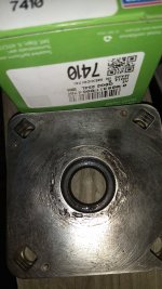
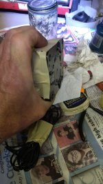
I rebuilt the steering box in my t5c this past summer due to excessive leaking and hard steering. It has a Hydraguide™ Hydrostatic Steering System. I used the HGF Series Service Procedure found in the Service Manual 2753. I ordered parts from QCC consisting of a bushing item 38 part no. 063042X1 and seal kit SK000097. I later found information that John Deere AM107078 seal kit is a substitute for Parker SK000097 seal kit but have not confirmed this. The procedure was fairly easy to follow but the springs inside the box were very hard to keep from flying off when opening the box up and even harder to keep in place during reassembly. Be aware that the 2 sets of 3 springs each are different lengths and go in different locations. Manual had no recommended way to hold the 3 problem springs in place during reassembly see attached IMG_20220618_171631188 showing my solution. If your steering box has item 52 a 9/32" steel ball be extra careful that the ball is in its chamber toward the center of the box when the item 2 Port Cover is reinstalled. My mistake was thinking that the ball would move freely from one end of the chamber to the other, this is not the case as I found out after reassembly and reinstalling the box on the tractor only to discover that the power part of the power steering was inoperative. After troubleshooting the steering pump and finding the pressure okay I had to remove the steering box and disassemble it and get that ball in the right location. The manual neglects to give this important detail in step 41A of the assembly instructions. After getting this check ball in the proper location the steering is working great with no leaks. Something to consider to save time and possibility of screw ups is skipping the steps on disassembly of the commutator, I considered carefully doing these steps but the thought doing the readjustment of this device seemed daunting and probably unnecessary as the commutator seemed to turn freely with no binding and since the box interior showed no metal or debris I elected not to do the commutator steps but that is your choice do it you want to do it. I did do a couple of things not called for in the manual which you may consider if you think it makes sense. I added a fitted grease seal where the steering shaft passes through the item 32 Upper Cover Plate. I also used a thin layer of silicone sealant between the shaft tube flange and item 32 Upper Cover Plate. My reasoning on doing this is I found corrosion damage in this area as seen in the photo (See attached IMG_20220615_171231059 for part # of seal). These boxes have a problem of oil leaking up the steering column and out from under the steering wheel this grease seal adds back up to the primary seal and along with the silicone sealant will help to keep water that may get into the shaft tube from entering the box. Good luck.
 

Attachments

  • IMG_20220618_171631188.jpg
    IMG_20220618_171631188.jpg
    1.6 MB · Views: 77
  • IMG_20220615_171231059.jpg
    IMG_20220615_171231059.jpg
    2 MB · Views: 77
 
Top