Reading my JD-790 hydraulic schematic...

/ Reading my JD-790 hydraulic schematic... #1  

Willl

Elite Member
Joined
Jul 22, 2006
Messages
4,408
Location
Northwest, WA
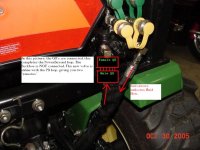
Got some questions about my JD-790 hydraulic schematic and valve plumbing. (see attached)
The tractor has FEL, BH and rear PB ports. (BH runs off rear PB ports)

1) Beings my 790 has a SCV, to make this schematic less cluttered and easier to read, the lines I marked 1 and 2 are unused and I could erase them, correct ?

2) If I'm reading this correctly, this 790 SCV valve has both a PB output and a 'return to tank' output ?

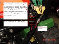
3) If I was to install an extra hydraulic valve(s) off the rear remotes, would it
also have/need a 'return to tank' output ?
Obviously it'll need a PB output plugged into the return to power the rockshaft. Am I also going to have to plumb a extra 'return to tank' line from the new valve ?

4) If 3 above is 'yes', does the 790 have a 'return to tank' port ?
 
Last edited:
/ Reading my JD-790 hydraulic schematic... #3  
Anybody ?

I believe that with all valves using PB, the work port fluid from each valve has to return to tank.
 
/ Reading my JD-790 hydraulic schematic...
  • Thread Starter
#4  
Hmm, so beings my BH has only 1 return it has to be a 'work port outlet' correct ?, which means my add-on valve must go before the BH ?

So looking at my schematic, does this also mean that as long as my BH is hooked up, my 3pt is nonfunctional ?
 
/ Reading my JD-790 hydraulic schematic... #5  
O.K..... I think you are right on the schematic, but with that confusing thing aside......
A power beyond circuit always is constant live pressure and has to have 'return to tank' port. If you were to put a valve in a PB circuit, it must be an open center valve so you do not dead head the tractors pump when the valve is not open. The out or return port of the valve could then then go to the work port "inlet" of the BH valve OR back to the tractor via "work port outlet hose" of the power beyond. OR add-on valve could go AFTER the BH with work port outlet to the 'in' port of add-on valve and the 'out' port of the valve to the work port outlet line to the tractor.
The 3pt should still work with the BH or PB. Not that you could use 3pt implements with the BH in the way......
Mech put top/tilt and hydralic angle loader blade using the PB on his 790. He did a most excellent photo and description of the whole deal. A search on that might help 'ya to.
 
/ Reading my JD-790 hydraulic schematic...
  • Thread Starter
#6  
I reworked my schematic.

I went on the assumption that lines 1 and 2 were not applicable in my case and erased them. It does unclutter it a bit.
I also added where my backhoe is plumbed in at.

Couple things I noticed studying this, the rock shaft is the very last guy on
the line and there's not a whole lot of difference between a PB port and just tee'ing into the line. Sort of.
 
Last edited:
/ Reading my JD-790 hydraulic schematic... #7  
Will,

Here are my thoughts...

First, what threw me was this statement (hence my PM to you):
The tractor has FEL, BH and rear remotes. (BH runs off rear remotes)
Just a terminology thing, but you do not have "rear remotes", you have what everybody calls "power beyond". "Remotes" usually means a valve, witch you do not have.

So now you want a rear remote valve... All you need is a valve without PB, and plump it in to the PB "loop" that you already have. If have done this on my machine, as well as quite a few others with JD's.

You will have to decide if you just want to lug the new in and use it when the backhoe is removed, or make it permanently plumbed in.

Look at these three threads:
Mine
Brad's
Jim's
 
/ Reading my JD-790 hydraulic schematic...
  • Thread Starter
#8  
Thanks for replying Kenny.

Just a terminology thing, but you do not have "rear remotes", you have what everybody calls "power beyond". "Remotes" usually means a valve, witch you do not have.
Yes, your correct. I should have called it PB instead and have corrected it.

I guess what's getting me confused is/was my thinking that a 'second' inline valve must be fed from a PB outlet from the first valve ?

Ya, permanent mount and permanent plumbed.
 
/ Reading my JD-790 hydraulic schematic... #9  
wow....this was interesting...
First I must say after using JD educational litterture for many years, they are top of the line....
so is this drawing, even if JD seems to step away from the ISO standard a little bit.

I have a question to you guys, with experience of these JD tractors.
It is about the filter setup. I have never seen a design with a strainer in the tank, and a filter with a by-pass on the suction line. and no filter on the return line.
Is this a standard JD Tractor design or did the JD engineer make a mistake in the drawing, putting the filter on suction line instead of return line??
It wont effect the power steering pump because it is closed loop, but for sure the FEL, Rockshaft and AUX pump circuit.
See my picture!
If this is the design, it will for sure set up for a possible pump cavitation!
jdsuctionfilter.JPG
 
/ Reading my JD-790 hydraulic schematic... #10  
I guess what's getting me confused is/was my thinking that a 'second' inline valve must be fed from a PB outlet from the first valve ?

Here is the way I look at it...Does your backhoe valve have a PB port? How many hoses are connected to it?

The main problem on the JD's is that the FEL valve is mounted directly to the transmission case (unlike most other makes) and does not have ports like a regular valve...The PB kit that you have is really all we have to work with.

IF you can find a "tank" port on your machine, then you can use a PB equipped valve with the PB port feeding the backhoe and/or the 3PH.

Attached are two pictures from my album that I marked up for another user. Basically there are QD's on the IN side of the new valve where you would plug in the backhoe. I am thinking of changing my setup over the winter like this so I can add a 3PH logsplitter., and I have the QD's from the original PB kit that I never used.
 

Attachments

  • SCV No BH.JPG
    SCV No BH.JPG
    93.6 KB · Views: 1,411
  • SCV with BH.JPG
    SCV with BH.JPG
    111.2 KB · Views: 1,725
/ Reading my JD-790 hydraulic schematic... #11  
AKKAMAAN,

Why do you think that is a mistake. that is the way just about every Power-Tracs are plumbed, except for the tank strainer. The filter is located right before the charge pump for the closed loop VSP, and so far works quite well. I have also read that suction filters are not a good idea, but they are being used. I understand that if they clog, the pump may suffer, but that is why the bypass. Our machines do not have a return line filter. I would assume their thinking was, that if any crud were in the system it would go to the tank, and settle out, and since the suction line is above the bottom, and then it gets filtered before it gets into the transmission, and wheel motors.
 
/ Reading my JD-790 hydraulic schematic...
  • Thread Starter
#12  
Kenny, this quote from the other thread clears up a lot, thanks.

Since the functions would be mostly used one-at-time, just putting them in series without PB is perfectly fine.
 
/ Reading my JD-790 hydraulic schematic... #13  
AKKAMAAN,

Why do you think that is a mistake. that is the way just about every Power-Tracs are plumbed, except for the tank strainer. The filter is located right before the charge pump for the closed loop VSP, and so far works quite well. I have also read that suction filters are not a good idea, but they are being used. I understand that if they clog, the pump may suffer, but that is why the bypass. Our machines do not have a return line filter. I would assume their thinking was, that if any crud were in the system it would go to the tank, and settle out, and since the suction line is above the bottom, and then it gets filtered before it gets into the transmission, and wheel motors.


Thank you J_J!
I am looking at this with out of a "general" point of view. And I have never seen this set up before. My experience is a little limited to heavy equipment though.

The reason a strainer is a bad idea is that it increases risk for cavitation, so that's why I cant see why a filter, with higher flow resistance than a strainer, is a good idea....It kinda multiplies the risk...and now I see both a strainer and a filter on the suction side....

But I didn't say it is a mistake, I just wondered if it was a mistake, or the real design........and now you verify it is plumbed this way....thats fine....If it works it works.....

I am just curiuos about what reason JD have for this design, when it has been custom for ever on heavy equipment, to have the filter on return side, and/or on the pressure side of pump? I also wonder what that by-pass setting is, and the filter size and "filtration-rating"....

A return filter takes care of everything, pieces of rubber, seals, metal etc, coming bac from the system. Also not to forget the dirt exposure, when repairs are done on hoses and cylinders etc..With this current disign , all this stuff will get trapped on the suction side, and starting to increase vacuum in suction line......with un scheduled maintenance will follow, if operator is good enough to catch it......

The strainer discussion have been going on for a long time (for ever), and I believe strainers are necessary on equipment in dirty environment and and on equipment that don't allow "safe filling of oil", but they should also be mounted under the fill cap....In very cold climate strainers should not be on suction side...neither a filter with by-pass.....
 
/ Reading my JD-790 hydraulic schematic... #14  
The suction filter on my Power-Trac is 10 micron . What puzzles me, is that the other two pumps have no filter, and pull fluid from the tank. Eventually, all the fluid in the 20 gal tank will be filtered by the charge pump. So I guess you could say that the two other pumps were pulling filtered fluid, although indirectly. At about 5 GPM through the charge pump circuit, that would be about 300 GPH. So the tank/reservoir fluid would be changed out at the rate of 15 times per hour.

If a return line filter should began to clog, that would set up some back pressure and cause some problems.
 
/ Reading my JD-790 hydraulic schematic... #15  
Kenny, this quote from the other thread clears up a lot, thanks.

I am going to repeat my self here, it is not a good idea to put valves in series, as the return ports are not designed to handle high pressure. That is not to say, that some valves can take the pressure based on the amount of material around the return port. It can be done and has been done, and some fail and some don't, so take your chance, and be good enough to let me/us all know when it fails.

I had read this before in the technical manuals, but the engineers at Prince are sending me the reference for this.
 
/ Reading my JD-790 hydraulic schematic... #16  
The suction filter on my Power-Trac is 10 micron . What puzzles me, is that the other two pumps have no filter, and pull fluid from the tank. Eventually, all the fluid in the 20 gal tank will be filtered by the charge pump. So I guess you could say that the two other pumps were pulling filtered fluid, although indirectly. At about 5 GPM through the charge pump circuit, that would be about 300 GPH. So the tank/reservoir fluid would be changed out at the rate of 15 times per hour.

If a return line filter should began to clog, that would set up some back pressure and cause some problems.

Well, compared to cavitation, backpressure from return line filter is unheard of as a problem....Is there 3 pumps....I could only see two on the drawing....Another drawing??
BTW "charge pump"= Power steering pump?? or what?
 
/ Reading my JD-790 hydraulic schematic... #17  
Sorry about any confusion, I deviated from the thread a little, but

I am talking about my Power-Trac, because it has three pumps, in ref to the suction filter, and no return filter.

I would venture a guess that most Hydrostatics would have a suction filter.
 
/ Reading my JD-790 hydraulic schematic... #18  
Well, compared to cavitation, backpressure from return line filter is unheard of as a problem....Is there 3 pumps....I could only see two on the drawing....Another drawing??
BTW "charge pump"= Power steering pump?? or what?

Agreed, I've never seen an issue from a clogged return filter. But, all that I have seen have a bypass in the mounting block.

I've worked with some people from Caterpillar the past few years, mainly on the hydraulic side. They told me that they are way more concerned with contaminants entering the pumps than getting into the tank. Stuff getting into the tank, via the breather or from added oil, is a much larger concern than contaminants entering the tank from the rest of the system.

The machines over time have needed to be more compact and more powerful. There is only one way to accomplish both, more hydraulic pressure. The way they wanted to increase hydraulic pressure and efficiencies is by tightening up the tolerances. So now, those little particles in the air that enter through the breather everytime a cylinder is filled with oil are in the hydraulic oil. The old way, the oil had to circulate through the entire system until it got to the filter. By placing the filter in the suction side, they have the filtering they need with the tighter tolerances in the pumps, valves, and other components.
 
/ Reading my JD-790 hydraulic schematic... #19  
I am going to repeat my self here, it is not a good idea to put valves in series, as the return ports are not designed to handle high pressure. That is not to say, that some valves can take the pressure based on the amount of material around the return port. It can be done and has been done, and some fail and some don't, so take your chance, and be good enough to let me/us all know when it fails.

I had read this before in the technical manuals, but the engineers at Prince are sending me the reference for this.


I guess all the people here on TBN and elsewhere with electric solenoid valves (like the WR Long kit) and backhoes plumbed with just two (IN/OUT) Power Beyond hoses better be on the lookout for flying shrapnel then since their systems are doomed to failure.

Fact is, in the real world-valves are hooked up in series all the time with no ill effects. When was the last thread on a valve that cracked?
 
/ Reading my JD-790 hydraulic schematic... #20  
I guess all the people here on TBN and elsewhere with electric solenoid valves (like the WR Long kit) and backhoes plumbed with just two (IN/OUT) Power Beyond hoses better be on the lookout for flying shrapnel then since their systems are doomed to failure.

Fact is, in the real world-valves are hooked up in series all the time with no ill effects. When was the last thread on a valve that cracked?


NO, the fact is, why would they build valves with PB if valves in series work just as well. Just because you can, doesn't mean you have to, or should. If you can show me a reference that any manual valve should be connected in series I would appreciate it.

Return, means return to tank.

I have never had a valve explode on me either, but then again, I don't put them in series.

If the specs on the valves are the same for the input and return, you might get away with it. but I don't believe they are. The Prince engineers said that all their valves return ports should go to tank. In a normal situation, the output from the return port is low pressure.

I never said anything about solenoid valves.

If you want to preach that data as gospel, that is your choice.

There are things we do things out of the ordinary, so do as you will. If it works, fine.
 

Marketplace Items

2022 Mack Anthem T/A Wet Kit Day Cab Truck Tractor (A61568)
2022 Mack Anthem...
UNUSED SDLANCH BI-PARTING WROUGHT IRON GATE (A62131)
UNUSED SDLANCH...
UNUSED JCT 72" HYD ANGLE BROOM (A62131)
UNUSED JCT 72" HYD...
(2) 30 Yard Dumpsters (A61166)
(2) 30 Yard...
UNUSED WOLVERINE RPR-12-72W 72" RIPPER (A62131)
UNUSED WOLVERINE...
2022 John Deere X730 Lawn Mower (A63116)
2022 John Deere...
 
Top