Hydronic heat, I broke it.

/ Hydronic heat, I broke it. #1  

widefat

Platinum Member
Joined
Oct 7, 2015
Messages
702
Location
Central Va
Tractor
Kubota L3200 Husq GT52XLS Husqvarna LC121P Husq 455 Rancher Stihl FS90 Stihl MS170 99 Ram 1500
Throw out some ideas - nothing is too simple; talk to me like I am 5 years old.

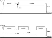
It is a one pipe main system.
Two zones
I believe the pressure differential is 6lbs.

Everything worked until I messed with it.

The problem -
Water is not flowing through one section of radiators.
At each end of the feed, the main pipe is hot.
The changes - along one wall, I had one long radiator. I added a door in the middle of the wall.
To accommodate the door, I cut a section out of the radiator.
I dropped a section of pipe down underneath the doorway , through the crawlspace, and back up to the other side of the door.

I attached a drawing - note the pipe sizes.
Also note that now the water will not flow at all, from the beginning of the pic to the end, even through the unmodded radiator
So why wont water flow now?


hyd sys.jpg
 

Attachments

  • hyd sys.jpg
    hyd sys.jpg
    27 KB · Views: 263
Last edited:
/ Hydronic heat, I broke it. #2  
Sooo.... the top pic is the system down one wall - bottom picture is down the other wall. My guess is an air block somewhere in the system. Is there a valve somewhere that was accidentally closed. What about the circulating pump - is it still OK.
 
/ Hydronic heat, I broke it.
  • Thread Starter
#3  
Sooo.... the top pic is the system down one wall - bottom picture is down the other wall. My guess is an air block somewhere in the system. Is there a valve somewhere that was accidentally closed. What about the circulating pump - is it still OK.

I changed the pic - the pic shows the radiators before and after my changes.
The circulating pump still supplies the rest of the house fine.
 
/ Hydronic heat, I broke it. #4  
Is the air bleed valve on each side at the high point and have you bled them sufficiently? It looks like you've created a "P-trap" and this is most likely your problem preventing flow. One of our TBN resident plumbing guru's will be along shortly to give us the "skinny".:)
 
/ Hydronic heat, I broke it. #5  
Which way does it flow?
Shot in the dark here, but did you changes change the way it needs to be bled?
 
/ Hydronic heat, I broke it. #7  
If you're showing one leg vs all of the system, we have net flow through a 1/2" pipe that has just had four 90s added to it.

If this is a 'branch', then the extra turns are adding that much to flow restriction to it. If this were a hydraulic circuit, a flow divider would be indicated.

An extra circulating pump can be added to a branch, but while it might improve flow in the portion shown it might then deprive other areas.

What are/were we using for zone control already? IMO, 6 psi PD should push air out unless flow rate is too slow.

Inquiring minds might want to see a flow chart of the whole installation for perspective.

btw, "radiator-free" for 15 + yrs, and I don't miss the dusty fins, air bubbles, expansion tank, hassle to vacuum around, or boiler maintenance. (nat gas)
 
/ Hydronic heat, I broke it. #8  
A couple of questions;

You say the rest of the house is still working off the circulator,
is it a single circulator with multiple loops?

You may be able to get away with adding a bleeder at the end of the trap you created,
that would be on the left hand side of the right most radiator in your drawing.

Many times with one circulator on multiple loops they will require balancing valves to achieve the proper flows.
Restricting the flow to the easiest flowing to push the flow through the more restrictive loop.

Also depending on who and how your system was set up it was not unusual for the circulator to be pulling thru the system and pushing back into the boiler.
This type works well but is easy to airlock.

When you state a 6 pound pressure differential is that a differential in the system or 6 pounds overall, my auto fill maintains almost 15 psi in the system.
To see the differential from the circulator would require a differential pressure gauge or 2 gauges one on each side of the circulator.
 
/ Hydronic heat, I broke it. #9  
I agree with Old Grind and Lou. The system probably needs a bleed at the high spot where it comes up from the crawl space. In the p-trap you created.

And, adding four 90 degree elbows added a flow restriction to this circuit that is not present in others. So you might need to balance this circuit with the other. Maybe an easy way to do that is to add a gate valve to the other circuit. Slowly close it until both systems have equal flow.
 
/ Hydronic heat, I broke it. #10  
Since a stalled or blocked (centrifugal!) pump sees less resistance and does less work (hear your shop vac freewheel and rev up when blocked?) there is no harm, hassle or waste by adding individual pumps to flow-restricted branches to aid flow and/or purging.

My hydronic system (1800 sq ft home) was replaced with forced air and I saved the Taco circulating pump, a whopping 1/25 hp that at most would draw .70 amps at 120v.

(.7 a = >1k hour run time per kw used, ~ $.15 here)
 
/ Hydronic heat, I broke it. #11  
Find the highest point in your new change and remove the nipple that is there and install a bleeder nipple.
 
/ Hydronic heat, I broke it. #12  
Ah - ha. There are multiple loops in this heating system. You have just added restrictions in this loop. As "the OldGrind & LouNY" indicate - you will probably need flow restriction valving to get adequate flow back into this loop. Even inside a closed circuit - water will take the path of least resistance.
 
/ Hydronic heat, I broke it.
  • Thread Starter
#13  
Two more drawings -

hyd sys 2.jpg

hyd sys 3.jpg
 
/ Hydronic heat, I broke it. #14  
WF - is that bottom drawing correct? You have a main loop( heavy black line) with a circulating pump in the loop. Each of the radiators is a separate loop off that main loop? How does water flow out and thru each of the individual radiator loops?
 
/ Hydronic heat, I broke it.
  • Thread Starter
#15  
/ Hydronic heat, I broke it. #16  
Just wondering after you cut, drained, installed the new radiator & piping; how did you initially refill & bleed that loop?

I'm assuming your one pipe system uses Diverter Tee's (MonoFlow Tee's) in it at each radiator loop off the Main System loop. This system is much tougher to bleed when air is trapped in one of the radiator loops. Using just the bleeder vavle in the radiator loop my never work or take an extremely long time to bleed. Water will take the least pass of resistance & with an air lock in that loop most of the water will flow past the Diverter Tee & travel straight through the Main System Loop.


This may help:

(1) If you have the ability to shutdown each radiator loop off the main loop I would shut them all off first (your system may not have this)
(2) Then shutdown the Main Loop Return
(3) Then Open the Bleed Valve on the radiator loop you just modified
(4) Slowly (SLOWLY) add water to pressurize the loop forcing the air through it.. You don't need the boiler running to do this...

Go slow... these system take awhile to bleed... after you think you have most of the air out of that radiator loop Close that loop also

With ALL of the radiator loop closed off the Main Loop - Bleed the main Loop again..

Then fire the boiler & have the system call for heat... I would then carefully open & bleed each of the radiator loop again individually...
 
/ Hydronic heat, I broke it. #17  
With mono-flow tees at each diversion, the newly installed drop will likely never self bleed or purge the trapped air.

If diverter tees are NOT fitted, it's worse '-)

There are no shut off valves shown in the system layout. That sucks. because if the flow could be forced through the modified loop, circulation could be restored. At least until "new air" gets caught in the natural trap.

A simple bleed at each elbow of the modification might be enough to get things moving through the loop.

I can't think of a reason to use caution or to go slow with your efforts. but don't expect immediate improved results without getting in and making changes.

Diverter tees are stupid devices.
 
/ Hydronic heat, I broke it. #18  
I agree, Most likely got an air lock in the system
 
/ Hydronic heat, I broke it. #19  
This stuff was my trade for 30 years. Probably an air lock but! I would never try to diagnose this without seeing the system. An air bleed needs to at every high point of the system. I would need to see the finned pipe enclosure to determine how to accomplish such. Air does not circulate in a closed system as it pockets in the high points blocking flow. Bleeding a cold system is a start, heating the water releases the dissolved in the water until there is no more. Several bleedings may be required to get rid of it all. Your drawing exhibits at least one bleed valve in the wrong location, maybe. We used to tip the finned pie a little down toward the input side to push the air to the outlet connection.

Zone pumps and closely spaced tees or diverter tees help smooth out a system(s). Engineering on these systems has gone through a lot of changes over the last 30 years. Like is your boiler make-up water feed automatic or manual? A leaky system keeping water flowing in on an auto feed also keeps introducing air and nobody notices like on a manual feed which shuts down on low water. Continuous water feed will also shorten the life of the boiler and components due to oxygen created acidic corrosion among many other potential problems. The average homeowner has no clue about water chemistry and water treatment of hydronic systems.

You are possibly beyond the DIY stage unless you have a knowledgeable friend or neighbor. You may find some helpful system drawings on the internet. I gave a way ll that stuff long ago.

Ron
 
/ Hydronic heat, I broke it. #20  
You need a high point vent. Home Depot sells them...
 

Marketplace Items

2010 Freightliner M2 106 Pac-Mac KBF 20H Forestry Grapple Truck (A66736)
2010 Freightliner...
JOST FIFTH WHEEL PLATE (A64276)
JOST FIFTH WHEEL...
2019 JOHN DEERE 750K LGP CRAWLER DOZER (A65056)
2019 JOHN DEERE...
ALLMAND MAXI-LITE II V (A68842)
ALLMAND MAXI-LITE...
2014 Club Car Golf Cart (A62613)
2014 Club Car Golf...
CRATE OF FLANGES AN PIPING (A67714)
CRATE OF FLANGES...
 
Top