Hydraulic Tank Design

/ Hydraulic Tank Design #1  

Wild Bill the 2nd

Gold Member
Joined
Jan 18, 2015
Messages
358
Location
So. Tier NY
Tractor
Kubota L6060, RTV 900XT
I am working on a firewood processor and am looking to build a hydraulic tank. I had some questions, in particular about baffle design.

Note: The processor will have a 17 GPM saw pump, 6.5 GPM pump for misc cylinders, and a 28/7 GPM 2 stage pump for the splitter. That is up to 51.5 GPM.


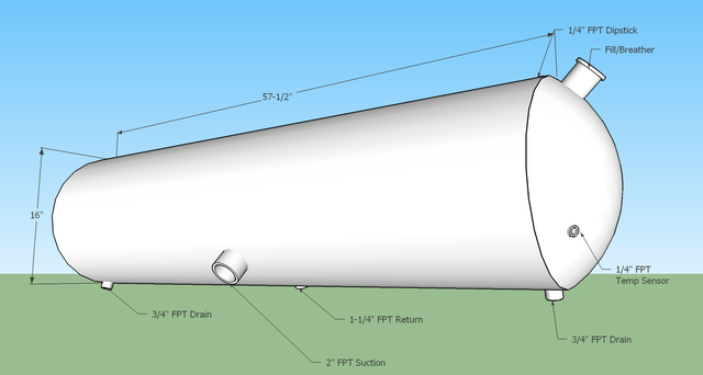
Here is my current design. Work has some 16" OD dished lids that are scrap due to the metallurgical properties not being correct. At 16" Dia. you get 1.15 gal per inch of length. I have roughly decided on a 50 gallon tank which comes to about 57.5" in length. (I am not including the amount of fluid in the dished ends in my calculation, it is extra capacity) I was thinking we'd fill it with 40 to 45 gallons. I have a 2" suction port and a 1.25" return port, two 3/4" drains, and two 1/4" fittings for a temp sensor and a dipstick.


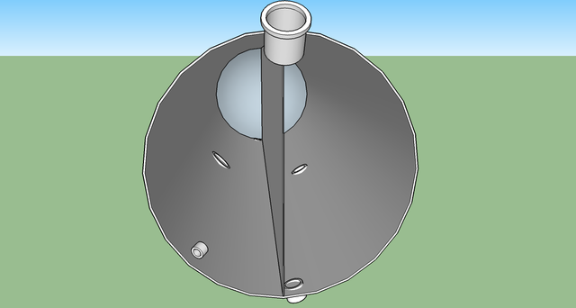
This pic shows the dished end removed. My plan for the baffle was to have it run top to bottom the full length of the rolled tank. Return comes in on one side of the baffle and the suction is on the other. The fluid will be forced to travel to the dished ends to get back around to the suction side.

I think the tank will have a lot of surface area for the volume of fluid. I'm not sure if that will allow us to get away without a hydraulic fluid cooler due to the shear GPM the pumps will be putting out.

Opinions on anything? Baffle? Port sizes/qty? Tank volume? Think it will work? Am I missing anything?
 
/ Hydraulic Tank Design #2  
I'm no expert at all but from the crash course I've been subjected to over the past couple months, I'd say you're going to need a cooler with that much flow. 1 gallon per GPM flow on low pressure but 3 gallons per GPM flow on high pressure.

Baffles are also usually only half to 2/3 high on bottom port tanks. That's what all the diagrams I saw showed while researching building my tank. In the end, I got a used one for less than the materials would cost to build one. I ended up with an aluminium 75 gallon tank for roughly 2/3 the cost of the materials to build a 35 gallon steel tank. Now if you're getting some if your materials for free, it might be different. I simply stopped by a heavy truck repair shop and walked around the yard with them, they didn't even know about all the tanks they had.
 
/ Hydraulic Tank Design #3  
You must ensure that enough oil gets around or past the baffle to prevent one side from over flowing while the other is empty. Possibly add a large hole at each end a couple inches off the bottom for some sediment settling. Yes on having returns on one side and suction on opposite side of the baffle.

Tanks reject very little heat with out adding cooling fins and air movement.
 
/ Hydraulic Tank Design #4  
And be sure the returns are BELOW the oil level, either entry below or with drop tubes. CJ
 
/ Hydraulic Tank Design #5  
Are you sure it is 1.16 gal/inch? I get 0.87.

Baffles separate the tank into two parts: one where the return enters that is always disturbed due to the return; the other where the fluid is somewhat less disturbed for a short time to allow contaminants to settle out and air to release from the fluid. It seems like that would work best if the path between the two parts of the tank were along the floor of the tank, which is accomplished if the baffle is say an inch or so above the bottom. That way the least disturbed fluid in the return part, which is presumably at the bottom, will be traveling to the suction part along a long slot that does not create more agitation.
 
/ Hydraulic Tank Design
  • Thread Starter
#6  
My mistake. It is 1.15 inches per gallon. You are correct .87 Gal per inch. Dimensions are still correct though.

My thoughts on the baffle was to place the intake and return on opposite sides and make the oil go around the plate at the ends. I was hoping to increase flow across more of the tank surface in an attempt to increase cooling. But I realize that might be a lost cause. I like the idea of adding fins though. That is a possibility. Then add a small electric fan at one end.

If I leave the baffle open at the bottom I would definitely need to move the supply and return to opposite ends of the tank. I'm fearful that would leave too much of a direct route between ports though. Maybe not.
 
/ Hydraulic Tank Design #7  
Leaving a gap at the bottom of the baffle would allow contaminates to travel easily from the return to the inlets. That is usually not a desireable feature in a reservoir.
 
/ Hydraulic Tank Design #8  
Can you plumb a small auto radiator (w/fan) into the 1 1/4" return line for cooling? (Use a 7.5psi pressure cap & route the overflow line to tank.) tog
 
/ Hydraulic Tank Design
  • Thread Starter
#9  
We can do whatever we want. Though I wouldn't run an automotive radiator in line with the return If I do that I will run a purpose built hydraulic cooler that is built to withstand the greater potential pressures of a hydraulic system.

If I do run an automotive radiator it would have a separate supply and return port welded into the hydraulic tank with a small pump of its own for flow so that it has virtually no pressure on it. In order for that to work I would need to see if the charging system on our two little tractor engines would support an electric pump for the fluid and a fan for the radiator. I kind of have my doubts.

The in line radiator thing has been discussed in some detail here. I just wouldn't trust a standard radiator to flow 50 GPM with surges from cylinders, motors, etc.
 
/ Hydraulic Tank Design
  • Thread Starter
#10  
Forgot to mention, I don't know that 3/8" ID tubing would handle the flow required if you had a 7.5 PSI cap. Not that I'd know for sure but I would imagine that regular unrestricted flow on the return line would top 7.5 PSI.
 
/ Hydraulic Tank Design
  • Thread Starter
#11  
Changed the tank design. We used the domed lids on our fuel tank.
Tank Hydro.png
We are going to use some 20" pipe and weld on some flat plate at the ends. The tank will have a divider running down the middle as before but it will be flush to one end of the pipe and have a 1" gap at the far end. The 1-1/2" return line will enter on one side of the plate and the 2" suction will leave on the other. Fluid will therefore have to run the whole length of the pipe and come back up the other side.

I would think that any air bubbles should rise in that distance. Any concerns with that layout?
 
/ Hydraulic Tank Design
  • Thread Starter
#12  
So we are at the hydraulics stage of the project and I am trying to figure out what grade hydraulic oil to use.
Viscosity requirements of my components allow for 13 cSt (60 SUS) to 54 cSt (250 SUS) with 32 cSt (180 SUS) being the ideal.

This would give me the following operating ranges for the following grades:
ISO 32 86-158 Temp Range and 104 is the ideal temp
ISO 46 104-170 Temp Range and 118 is the ideal temp
ISO 68 115-188 Temp Range and 135 is the ideal temp

We would ideally like to use the processor while the ground is hard. Either frozen or dry. My initial thought is to use a AW46 grade which would kind of be the middle ground for winter / summer use.

We are resigned to the fact that we will need a hydraulic oil cooler. We have 40 combined HP and with 25% - 30% system inefficiencies we would have 25,400 to 30,500 BTU/Hr of heat gain.

Our 50 gal tank has 20 square feet of surface area which will dissipate 1,600 to 3,600 BTU/Hr given a 40 to 90 degree differential between oil temp and ambient.

I am looking at a 22k to 32k oil cooler but it only has SAE 12 fittings. My return line is going to be 1-1/2" dia. My thought would be to break into my return line with a tee. Run a 3/4" line to the cooler. After the tee in the return line I add a ball or gate valve so I can add back pressure so fluid will want to flow through the cooler. Then I would have another tee after the valve where a 3/4" return from the cooler will re-enter the main return line.

So for feedback
1 Does my selection of ISO 46 oil seem appropriate given the stats and desired operating conditions?
2 Do the heat gain values look accurate / does it look like I've sized the cooler correctly?
3 Does the plumbing of the cooler make sense?
4 Do you think I'd be able to / should I use ISO grade 32 oil? Would I be able to maintain an oil temp of around 104 with the oil cooler in place?
 
/ Hydraulic Tank Design #13  
just catching your thread

i am more use to pond filters for goldfish/koi ponds. 1 of the DIY filters out there, is a gravity fed "vortex settling chamber", that is cylinder shaped. the goal of this filter, is for fish poo, leaves, twigs, to sink out to the bottom. and then normally a pond pump is placed after it. the over all goal is it is harder to filter out minced up fish poo if fish poo went straight into pump and get grounded up much like in a blender. vs filtering out the large fish poo chunks before it ever gets to the pond pump. the filter uses a "vortex" / whirl pool like current inside the tank. to help larger heavier stuff sink out. there are additional DIY / professional mods. for extra filtering within the center of the tank.

i am thinking a similar setup might help improve your overall doing for the hyd oil tank.

the vortex / whirl pool action, created by the inlet. should help force the air in oil to seperate some more.

i am guessing 5 to 15 gallon tank all ya really need. looking at other thread and your plumbing diagram. you are using motors and double acting cylinders. and no telescopic hyd cylinders that i saw. so once you get past the initial "filling" and bleed out air. you should not have a hole bunch of air in the system, if oil is good. and no suction leaks in the system.

google.... different key terms
DIY 55 drum settle chamber
vortex settling chamber
DIY 30 gallon drum SC

above should bring back a descent amount of videos and images and various diy plans folks have done for DIY pond filters.

==============
if you are going to stick with your current design. you should install some sort of defelector plates. on both inlet and outlets (coming / going from pump) or insert a pipe inside the tank that runs horizontally. with either a bunch of holes or slits cut into it.

the above is to keep from a vortex / whirlpool forming above outlet going to pump. and/or disperse the inflow current from the oil entering tank.

above is nothing new. it can be seen in pond filters, to chemical spray tanks (30 gallon types up to few hundered gallon tanks that get pulled by a tractor. goal is to reduce getting extra air into the liquid, what ever it may be.

==============
to note it. i am not crazy with you laying the tank on its side, as you have it pictured in this thread. to me you are asking for extra air to be entertained into the hyd oil. the simple vibration of engines running, to the nock and bashing of lumber going through machine going to cause a lot of surface agitation / splashing. tip it on end.

===============
i am un easy with you tie-ing the return lines together, and running both flows from both motors / hyd pumps. through oil cooler. if one system is rated for 3000PSI, and other is rated for max of 1000 PSI. you could get yourself in trouble. and cause the 1000PSI system to go over 1000PSI and or degrade 1000PSI system. so it only works at part of its potential.

above would not be an issue. but if oil cooler got clogged, or some sort of valve got shut. you may kiss the lower rated MAX PSI system good bye.

if everything was rated to handle max 3000 PSI this would not be an issue.

you can have the common hyd tank. but i would split everything else up. different oil coolers, lines, etc... so you can save cash on hyd cylinders and other motors that will not need to be rated for 3000 PSI hyd oil pressure.
 
/ Hydraulic Tank Design
  • Thread Starter
#14  
the vortex / whirl pool action, created by the inlet. should help force the air in oil to seperate some more.

i am guessing 5 to 15 gallon tank all ya really need. looking at other thread and your plumbing diagram. you are using motors and double acting cylinders. and no telescopic hyd cylinders that i saw. so once you get past the initial "filling" and bleed out air. you should not have a hole bunch of air in the system, if oil is good. and no suction leaks in the system.
Removal of trapped air is not a major concern since I agree with you that there shouldn't bee much in there in the first place. I was just mentioning that the fluid would have to flow 6 feet between return and suction lines so that hopefully it would rise to the surface before the suction port if it were there. There shouldn't be that many contaminants in a closed hydraulic system to require a vortex system, at least I've never seen one before that I know of. I will have a 10 micron filter on the return line before it enters the tank as well as a 100 micron screen on the suction side to prevent any large debris that enters the tank from damaging the pumps. I have 50 gpm of total flow, many people will say that you should size the tank so that you have 2x the gpm. Couldn't get away with only 15 gal unfortunately.

if you are going to stick with your current design. you should install some sort of defelector plates. on both inlet and outlets (coming / going from pump) or insert a pipe inside the tank that runs horizontally. with either a bunch of holes or slits cut into it.

the above is to keep from a vortex / whirlpool forming above outlet going to pump. and/or disperse the inflow current from the oil entering tank.
This is one of my major concerns. I will likely make some baffle to sit above the suction port to prevent a vortex.

to note it. i am not crazy with you laying the tank on its side, as you have it pictured in this thread. to me you are asking for extra air to be entertained into the hyd oil. the simple vibration of engines running, to the nock and bashing of lumber going through machine going to cause a lot of surface agitation / splashing. tip it on end.
I hadn't been too concerned with this as there are many systems on the market have square or rectangular tanks that have a much larger surface area open on top of the tanks. Ours, since it is a pipe, will actually reduce the surface area as its filled above the half way point. We were planning to fill it with 45 gal out of the 50 gal possible.

Hadn't thought of mounting the tank vertical for whatever reason. That is a nice space saving option.

i am un easy with you tie-ing the return lines together, and running both flows from both motors / hyd pumps. through oil cooler. if one system is rated for 3000PSI, and other is rated for max of 1000 PSI. you could get yourself in trouble. and cause the 1000PSI system to go over 1000PSI and or degrade 1000PSI system. so it only works at part of its potential.

above would not be an issue. but if oil cooler got clogged, or some sort of valve got shut. you may kiss the lower rated MAX PSI system good bye.

if everything was rated to handle max 3000 PSI this would not be an issue.

you can have the common hyd tank. but i would split everything else up. different oil coolers, lines, etc... so you can save cash on hyd cylinders and other motors that will not need to be rated for 3000 PSI hyd oil pressure.
All high pressure lines will be rated for 3000 to 3500 PSI minimum. The return will have a pressure gauge on it that will be referenced and the ball valve between the supply and return of the cooler would not be closed much, just enough to make sure that there is some flow through the cooler. The return line should run at 150 psi or less (should be much much less). The hose is very large as compared to the three supply lines. As there is very little restriction in the return line the pump will not make anywhere near 1000 PSI. The cooler is rated to flow up to 50 GPM which is all that my pumps put out. I just would not want to run that much flow through a 3/4" fitting as it would create too much back pressure for the return line.

Thanks for the input. Please let me know if you feel any of my reasoning or logic is flawed.
 
/ Hydraulic Tank Design #15  
are you going to tap into one of the outlets coming from one of the pumps (in parallel)... or are you going to run a hyd motor to run a fan for the cooler (in series) say before you Tee the outlets together via return line going to the oil cooler?

or are you looking to run an longer belt. between one of the engines / pumps / cooling fan for the oil cooler?

with pure amount of gallons of oil. it sounds like you might try to run some sort of "oilier" maybe for the hydraulic chain saw? to keep chain / bar cooled down?
 
/ Hydraulic Tank Design
  • Thread Starter
#16  
The oil cooler we're planning on getting has an integrated electric fan. No need to rig a belt driven or hydraulic powered fan.

For the bar oil we are planning on having a separate reservoir where we can use bar oil / engine oil / hydraulic oil as we see fit. We were going to use an electric fuel pump that runs 30 GPH at 4 PSI to supply the oil. After the pump we will have a .4 or .2 Cv needle valve to limit the flow down to a tiny trickle.

I am still working on how to switch the pump / flow on and off as the saw starts and stops. That is where a feed off of the hydraulic lines to the saw could be easier.
 
/ Hydraulic Tank Design #17  
Use 32 or 10wt hyd oil. Some of the power units and drilling rigs I work with in North Dakota have had to drop down to 5wt oil and mix it with the 10wt. I mix dextron with the hydraulic oil for a cheap alternative to Artic oil out there. The only way I would use a thicker oil is in extreme heat 100 deg and above. Size your oil cooler to take the full volume of oil from your system with a delta p of 10 psi or less [pressure drop] them be sure it has adequate BTU removal [doing it this way almost assures it will] also get it with a 30psi internal bypass installed for cold starts. The only time I have ever done a external bypass was for a 150GPM system to be able to build up some heat when the unit was idling for hours at a time in the winter. CJ
 
/ Hydraulic Tank Design #18  
I am still working on how to switch the pump / flow on and off as the saw starts and stops. That is where a feed off of the hydraulic lines to the saw could be easier.

A motor spool solenoid valve can switch the hyd off/on.

A proportional solenoid valve can vary the flow from 0 to max flow.
 
/ Hydraulic Tank Design
  • Thread Starter
#19  
Size your oil cooler to take the full volume of oil from your system with a delta p of 10 psi or less [pressure drop] them be sure it has adequate BTU removal [doing it this way almost assures it will] also get it with a 30psi internal bypass installed for cold starts.
Hydraulic Hose Flow.JPG
I sized my return line per this chart which as near as I can tell says that for 50 GPM through 1-1/2" line is the very minimum I could use for a return line.
The smallest MA series oil cooler that Southwest Thermal makes with a port size even close to that is the MA-232 which has -20 (1-1/4") ports. That cooler is rated for 94,000 to 148,000 BTU/Hr which is way overkill.
If this is the route I should take I need to find a different manufacturer or use a separate pump to run the fluid through the cooler.
If it matters this is not a commercial venture. We are just making this processor to service 4 families. We may run it for 8 hours at a time but it is not something that will see 16 hours a day for weeks and weeks.

JJ, I hadn't thought of a solenoid valve. If I did it all by an electrical switch it would be a lot easier. For now I may try to utilize a reed switch or something to sense the motor spool move into the run position.
 
/ Hydraulic Tank Design #20  
View attachment 434025
I sized my return line per this chart which as near as I can tell says that for 50 GPM through 1-1/2" line is the very minimum I could use for a return line.
The smallest MA series oil cooler that Southwest Thermal makes with a port size even close to that is the MA-232 which has -20 (1-1/4") ports. That cooler is rated for 94,000 to 148,000 BTU/Hr which is way overkill.
If this is the route I should take I need to find a different manufacturer or use a separate pump to run the fluid through the cooler.
If it matters this is not a commercial venture. We are just making this processor to service 4 families. We may run it for 8 hours at a time but it is not something that will see 16 hours a day for weeks and weeks.

JJ, I hadn't thought of a solenoid valve. If I did it all by an electrical switch it would be a lot easier. For now I may try to utilize a reed switch or something to sense the motor spool move into the run position.

Take that chart with a grain of salt so to speak. 1-1/4" is fine for 50gpm. Any 90's and fittings on the return side should be low pressure malable. Use 90's and nipples vs street els. I routinely run 70 gpm through 1-1/4 hose to the filter then 1-1/2" to tank. A dva35 valve is rated at 70gpm with a 1-1/4" outlet. I am building 2 70gpm systems for winch trucks and just completed a 60 gpm split system yesterday.
Anyway, Thermal Transfer has many coolers that will handle 50gpm at less that 10psi of back pressure. A MFR-30 has a built in cooling fan and 1-1/2" ports will remove 20k BTU, has a built in 30psi relief, built like a tank. This is $690. I use this cooler on almost all of my truck builds. Another one is MR-35-30 this one will remove 40K BTU has 1-1/4" ports and is $566 but you have to provide airflow, no fan.
If you are running a multi circuit pump you can cool the return off of the split system before you combine the flow to the return. Depending on how much cooling you need. [just another option] You can always add a cooler later if needed. If you can keep the circuits off of the reliefs [not deadheaded on the relief] you may not need a cooler. At least 2/3rds of the systems I build for mobile applications do not need a cooler. As long as the operator keeps the pressures below the relief setting. Once you deadhead a system most of the horsepower goes to heat instead of motion. CJ
 

Marketplace Items

2007 MACK CHN613 6X4 T/A DAY CAB TRUCK TRACTOR (A59909)
2007 MACK CHN613...
2017 CATERPILLAR 980M WHEEL LOADER (A62129)
2017 CATERPILLAR...
Kubota GR2020G (A63688)
Kubota GR2020G...
2017 Ford Escape AWD SUV (A61569)
2017 Ford Escape...
2006 STERLING AT9500 6X4 T/A 14FT DUMP TRUCK (A59914)
2006 STERLING...
2023 VOLVO L90H WHEEL LOADER (A64279)
2023 VOLVO L90H...
 
Top