how to build your own custom backhoe subframe

   / how to build your own custom backhoe subframe
  • Thread Starter
#191  
I "think" the woods sub frame 1020800 utilizes four tapped holes on the end of the axel housing on each side.
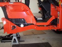
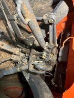
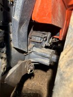
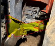
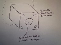
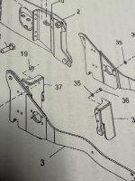
Yeah, it looks like the Woods subframe does use those holes. Is your axle housing made of cast steel or aluminum?

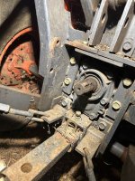
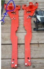
The parts diagram also seems to imply that your wheel hubs are easily removeable, with spline shafts or similar. That way you fit the axle thru the hole in your subframe.

I would stick with a smaller hoe (6.5') for your size B tractor.
 
Last edited:
   / how to build your own custom backhoe subframe #192  
Thanks for the response. It is aluminum. It appears that there are two issues I need to keep in mind in the design. 1. reinforce the frame from the FEL back to the rear end or even hoe, 2. be sure the attachment method of the custom sub frame to the rear axle housing is strong enough. Not really sure what the loads are on the tractor from a backhoe. I would think a sudden lift and release causing the front end to crash down is probably the most damaging but that's just a guess. Being most hoes have stabilizers that would help keep a lot of stress off the back end of the tractor almost making it a pivot point. That would actually be an interesting thread as I'm sure there are folks on here who know stuff like that :)

Jim
 
   / how to build your own custom backhoe subframe
  • Thread Starter
#193  
Not really sure what the loads are on the tractor from a backhoe. I would think a sudden lift and release causing the front end to crash down is probably the most damaging but that's just a guess.
The most potentially damaging forces on the tractor from the backhoe?

I would say it is the full force of the hoe applied to something like a tree stump that suddenly releases, or the lifting of the rear of the tractor that suddenly drops. Either activity can put sudden dynamic forces on the tractor that causes bending moments that are hopefully resisted by the subframe.

As for suddenly lifting the front of the tractor off the ground, that is not likely to happen with your B tractor, due to low flow and pressure of your hyd system. If you can lift the front at all, it would be slow and slight.

The challenge you have with your tractor is the aluminum castings at the rear do not really offer very robust threaded attachment points. This was a challenge for me with my larger stronger JD 4300. See above. The approach I took was to utilize the existing ROPS bracket in the rear to provide main support at the axle housings. You can also wrap the axle housings with your own custom fabrication.
 
Last edited:
   / how to build your own custom backhoe subframe #194  
The 3 point hoes did break some tractor transmission cases at the engine mounts. Any backhoe mounted on a tractor without a subframe is going to be lifting and pushing on the tractors "frame" or transmission cases and bell housing. The purpose of the sub frame is to remove that up and down loading on the tractor by securing the rear and front together with a "frame" so as to reduce the stresses on the tractors castings.
 
   / how to build your own custom backhoe subframe #195  
This all makes a lot of logic. Looking back that is surely why Kubota came out with the sub frame rails for both sides... not a true subframe but certainly help in strengthening the frame between the rear housing and the engine (FEL) section of the tractor. I think I will find/install these two sub frame supports regardless of how I design and build a full sub frame for a hoe.

As for reinforcing the axle housings by encompassing them in a metal contraption (box?) sounds easy enough. Especially if I use the four existing bolt holes as well. Something like making a metal cup that slides onto the axle housing extensions on each side and is in part held from moving by using the 4 bolt holes. Then put a couple of attachment points in it to attach to a 3x1.5 channel frame that goes up to the FEL and back to the hoe.

I will need to look again at the ROPS connection points to see if there is anything there that would work. At first glance it seemed too narrow as in my first picture and I thought the torque would be too much for it. Maybe not?

Let me see if I can draw something up tomorrow to help convey this idea.

Many thanks to you guys for helping me noodle through this one :)
 
   / how to build your own custom backhoe subframe #196  
Sorry for the delay - work. Ug.

The first picture is of the woods sub frame mounted on a B7500 which is about identical to the B2400. As I see it all the weight of the hoe would be on the axel 4 bolts on each side. I guess it's strong enough to hold it...

The rest of the pictures show my b2400 rear assembly at a couple different angles. The issue I see is the ROPS is very narrow where it finally comes to mounting on the rear assembly. Would using that point be an issue as the brackets would need to extend out to the left and right significantly to mount up to a4 point hoe? I would think there might be a torque issue here. I can see how the woods sub frame kit would not have that torque issue.

The last picture is an attempt to show the woods style subframe WITH ears that would extend onto the rear axle assemblies to give additional strength. Thoughts? Any idea how to utilize the ROPS mount instead? Open to all suggestions :)

Thanks, Jim
 

Attachments

  • woods sub frame photo.jpg
    woods sub frame photo.jpg
    409.6 KB · Views: 70
  • b2400 rear 5 toplink.jpg
    b2400 rear 5 toplink.jpg
    1.4 MB · Views: 69
  • b2400 rear 4 pto area.jpg
    b2400 rear 4 pto area.jpg
    2.2 MB · Views: 66
  • b2400 rear 3 axle.jpg
    b2400 rear 3 axle.jpg
    1.8 MB · Views: 61
  • axle with markings.JPG
    axle with markings.JPG
    218.3 KB · Views: 68
   / how to build your own custom backhoe subframe
  • Thread Starter
#197  
The issue I see is the ROPS is very narrow where it finally comes to mounting on the rear assembly. Would using that point be an issue as the brackets would need to extend out to the left and right significantly to mount up to a4 point hoe? I would think there might be a torque issue here. I can see how the woods sub frame kit would not have that torque issue.
I think your concern is valid, Jim.

The ROPS brackets on your Kub do seem to be farther inboard than I like. You will get some serious torque on the tractor when the hoe's outriggers are not exerting equal pressure.

If your "trumpet housings" are Al, I find those 4 small bolts somewhat concerning. I ran into a similar issue in the 2 subframes I made for JD 955s. That tractor had inboard ROPS mounts, but a cast steel trumpet housing. There was no option of attaching a subframe to the outboard part of the housing since there were only 3 tiny bolts.

So I made a subframe that wrapped around the housing, and clamped onto it. You could also add a brace to the ROPS bracket, but I did not.

The 955 subframes are above in this long thread, but here is one of them again
 

Attachments

  • DSCN0526.JPG
    DSCN0526.JPG
    1.6 MB · Views: 65
  • DSCN0527.JPG
    DSCN0527.JPG
    1.5 MB · Views: 64
   / how to build your own custom backhoe subframe #198  
That's genius! I do remember this now that you posted the pic again - I read the entire post a few weeks ago before posting my first thread. Do you see any harm in doing this to one that is aluminum? Maybe I do both: a wrap around AND put a plate on the end of it that has the holes for the bolts. Let me see if I can draw that idea up.
 
   / how to build your own custom backhoe subframe
  • Thread Starter
#199  
Do you see any harm in doing this to one that is aluminum? Maybe I do both: a wrap around AND put a plate on the end of it that has the holes for the bolts.
The Al-to-steel contact is a concern I have as well.

So....do both, yes. That is what I would do.
 
   / how to build your own custom backhoe subframe #200  
The way woods attaches their subframe at the end of the axle housing using the 4 pre existing bolt holes APPEARS to also be the way some of the kubota sub frames attached on the L series as best I can tell from the first picture. One key I had not picked up on is that both of them also have some type of extension that goes over to the ROPS or similar location for additional support (photo 1 is a kubota bracket and photo 4 is the woods diagram where you can see part 37) . I'm beginning to think that is the key: the combination of axle housing connection WITH a connection at the ROPS area would be pretty strong. So I'm not sure I need to go to the trouble to fabricate the axle housing reinforcement (photo 2) after all. The 3rd picture begins to put the system in place with a couple of options, but I really need to go measure some more as I don't want it to interfere with the 3 pt system.

One other option if I can't get some way to connect to the ROPS I might be able to put a spanner support across the rear at the bottom of the two long side brackets that connects to the draw bar area. Not sure what the weight rating is of that draw bar support bracket but I'm betting it's significant. See picture 5.
 

Attachments

  • frame extension to ROPs.JPG
    frame extension to ROPs.JPG
    66.7 KB · Views: 61
  • axle housing reinforcement.jpg
    axle housing reinforcement.jpg
    834.3 KB · Views: 60
  • mounting options 1 and 2.jpg
    mounting options 1 and 2.jpg
    955.7 KB · Views: 57
  • woodsframe2.jpg
    woodsframe2.jpg
    1.5 MB · Views: 59
  • drawbar spanner option.jpg
    drawbar spanner option.jpg
    697.9 KB · Views: 58
 
Top