Designing a bin tipper, sizing hydraulics.

   / Designing a bin tipper, sizing hydraulics. #1  

blakester

Silver Member
Joined
Jun 11, 2013
Messages
114
hey everyone, thinking about building a forklift bin tipper for the harvest this year. I was basically going to copy the design of one for the most part. The big question for me is figuring out how to size the hydraulic rams. My thought was to pilfer the side shift hydraulic function on the forks to act as the tipper function. No idea what kind of psi the unit puts out, though i suppose i could find the specs online somewhere. What's the right way to calculate how much pushing power i need out of the system?
View attachment 518417 440783196_544.jpg
 
   / Designing a bin tipper, sizing hydraulics. #2  
It depends on the geometry of the lift mechanism Vs cylinder size, pressure, etc.

You also geometry, the math version, to figure out what percentage of the cylinder thrust is used for lift based on the frame work geometry.
 
   / Designing a bin tipper, sizing hydraulics. #3  
Copying an existing design is simplest, or like oldnslo said start working out the forces and angles involved and to figure out what force your cylinder would need to generate to start lifting your crate. Then use a table to select your cylinder diameter. What forklift do you have? Might be able to find out the relief pressure by searching the model number. If you don't need the side shift you could disconnect it to feed your dump cylinder, or install a diverter valve so you can swap back and forth on the fly. If it's a triple mast then you'll have to get creative running the wires back to the seat for an electronic valve, but easier than running extra hoses.

Post pictures if you decide to go for it, always fun to watch other people's projects.
 
   / Designing a bin tipper, sizing hydraulics. #4  
Are you good at math?

First, you have to find the angle the cylinder is mounted at. And this is NOT what angle its at relative to earth. Its the angle in relation to what its pushing on.

Draw a straight line from the center of dumper pivot pin, THROUGH the center of the pin where the cylinder pushes. What is the angle of the cylinder in relation to that?

That can be worked out many ways, angle finder is easiest and gets close enough. But can use trig, (law of cosine) and do the math with just a few measurements.

Now that the angle is known.....you need to know the sine of that angle. Example ...... a cylinder mounted at 10 degrees.......the sine of that is 0.174 That means whatever force the cylinder can push with....17.4% is all the power you have for "dumping".

Example....2" bore cylinder on a 3000psi system. pie x radius squared x PSI gets cylinder force. = 6280#.

6280 x 17.4% = 1093 pounds of force to dump AT the location the cylinder is mounted.

Now we get out of trig and into simple leverage. Where is that mount positioned in relation to the center of the hopper?
If right in the middle.....then your average dump force for an evenly distributed load would be 1093#. But in your example, it looks like the cylinder is pushing only 1/3 the distance back from the pivot and not 1/2 way (centered). SO that leverage would further reduce the lift capacity to only 66%. 1093 x 66% would be about a 725# dump capacity with a 2" cylinder on a 10 degree angle @ 3000PSI.

Then you have to figure out how to mount a cylinder with a long enough stroke to get the dump angle you desire. More geometry and trig.

Ultimately you can use a long stroke smaller bore cylinder, or a shorter stroke and larger bore cylinder and arrive at the same dump power and dump angle. Or anything in between.

If any of this is beyond your skill level.....best to get some measurements and copy a design. And get good measurements. Because simply changing a pivot point by 1/2" or so can have a huge effect on cylinder angle and ultimately its power.

If you feel this isnt beyond your skill level and would like to try to work something out.....I am sure we can help you out along the way. But need as much detail as possible. How big is the hopper going to be front to back? How much do you want to dump?
 
   / Designing a bin tipper, sizing hydraulics.
  • Thread Starter
#5  
Thats great info guys thanks. I can definitely get going on the design and sizing. I will roughly copy the above picture for my design. The bins are grape bins, so 48" square and they will carry about a half ton of fruit. could be up to say 1500, but lets say 2200 pounds for a nice safety Margin. I'll have to dig up the specs for my Forklift. It's a 5000lb capacity Propane older one.
 
   / Designing a bin tipper, sizing hydraulics. #7  
I'd put a pressure gauge on the forklift first thing. Then I'd reverse engineer an existing one. Forklifts don't need much pressure on the lift cylinder, but tilt cylinders don't have nearly the leverage advantage so I'm guessing the system pressure is pretty high.
 
   / Designing a bin tipper, sizing hydraulics. #8  
I'd put a pressure gauge on the forklift first thing. Then I'd reverse engineer an existing one. Forklifts don't need much pressure on the lift cylinder, but tilt cylinders don't have nearly the leverage advantage so I'm guessing the system pressure is pretty high.
IIRC they run at 2500 to 3500psi in the lifts at work.

Aaron Z
 
   / Designing a bin tipper, sizing hydraulics.
  • Thread Starter
#10  
ok, rehashing my thread since it's time to start the build soon. Great feedback so far has led me to an update of my initial plans.
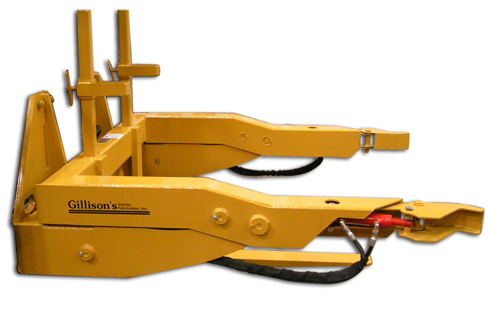
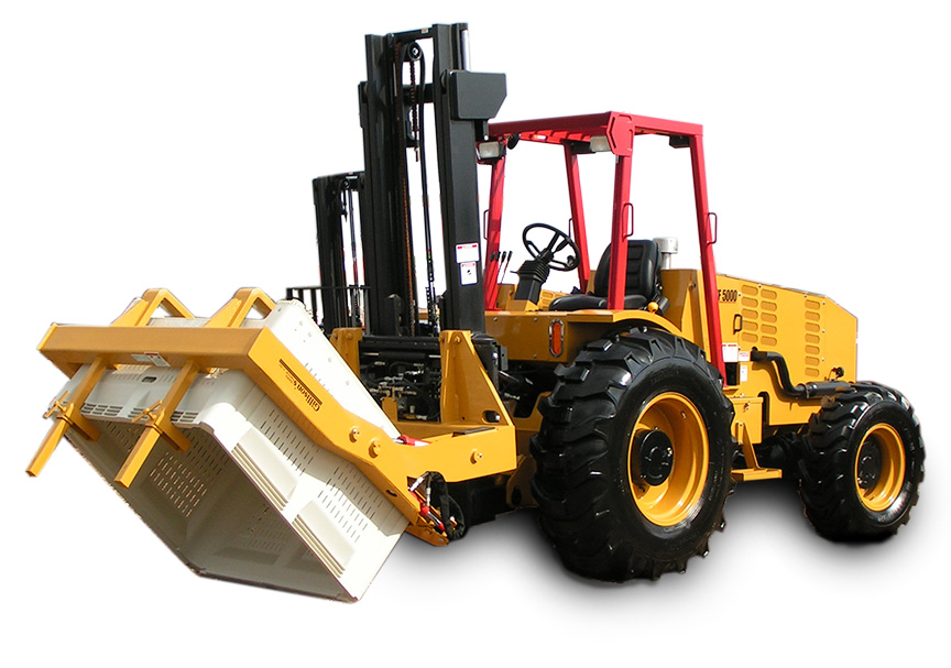
1. Changing from a forklift bin tipper to a standalone. I have figured it's going to be much more valuable to have the forklift available for other work.
2. This means a design change, but fundamentally keeping the same principal of where and how to tip.

So design's attached. Couple things I'm wondering about are the design of the attachment points for the cylinder. I see this tipping over when the bin is tipping with the center of gravity moving so far forward. Wondering about either tapering the legs, or adding feet. Thoughts? Also the big question for me is steel sizing. I feel like I know a couple of things here. 1. Depth (not thickness) is probably the most important for resisting force 2. Thicker is better )but not for my wallet). Is there a good "depth plus thickness = strength" guideline?

couple of bits of info.
1. This design is based off a 27" pin to pin retracted length with an 18 inch stroke.
2. Design is to scale, and functions mechanically, so reconfigration is quick, and should show me accurate results / problems.
3. Telescoping legs for height adjustment.
4. Pivot point for the pin (long steel pipe through some bushings? pillow block bearing?)tipper1.PNGtipper2.PNGtipper3.PNGtipper4.PNGtipper5.PNGtipper6.PNG
 

Tractor & Equipment Auctions

7’X20’ METAL FARM DRIVEWAY GATE (A45046)
7’X20’ METAL FARM...
2016 Bobcat T770 Skid Steer (A42203)
2016 Bobcat T770...
2010 APACHE TRAILERS INC. GOOSENECK TRAILER (A45046)
2010 APACHE...
TARTANS TORQUE MASTER MAKEUP & BREAKOUT MACHINE (A45046)
TARTANS TORQUE...
2014 WESTERN STAR 4900 TRI AXLE (A45046)
2014 WESTERN STAR...
2006 GMC 8500 Forestry Grapple Truck (A44571)
2006 GMC 8500...
 
Top