Mowing Cutter death trap

   / Cutter death trap #41  
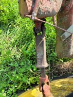
The drawbar length is crucial for proper PTO shaft engagement and operation. A 1000 RPM PTO system is typically found on more modern and higher horsepower tractors and is designed to handle heavier implements. The 16-inch measurement is a standard for 1000 RPM PTOs and ensures the PTO shaft can properly telescope and retract as the implement moves over varying terrain. This is especially important when using a three-joint driveline on a drag implement, where the tipping bearing should be close to vertical on level ground with the correct drawbar length.

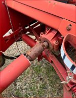
Anybody remember the special hitch JD used on the balers? Special adjustable casting the slipped over the drawbar and extended it to about 1/2 the length of the PTO shaft.
 
   / Cutter death trap #42  
I'm under the impression that distance should be 14" for a 540 rpm and 16" for a 1,000rpm shaft.
That is per maiuk in 2010.
Incorrect. It requires equal co-linear AND co-planar alignment of the input and output shafts, with the center of the intermediate shaft being over the hitch pin. This is for Non-C.V. jointed drive shafts.

BTW: Here is an example of a non-zero phased drive shaft found in many hay rakes where the axle stub is NOT aligned with the gearbox stub. An angle is installed on the intermediate drive shaft to compensate for the mis-aligned (non-colinear) mechanism. Other examples of non-zero phased shafts are in the steering system of FWD cars. This is needed because the steering column does not line up with the pinion of the steering gear. This condition exists for crashworthiness reasons so a frontal impact does not punch the driver with the steering wheel during a collision.
 

Attachments

  • 20250708_161403.jpg
    20250708_161403.jpg
    7.6 MB · Views: 37
   / Cutter death trap #43  
Incorrect. It requires equal co-linear AND co-planar alignment of the input and output shafts, with the center of the intermediate shaft being over the hitch pin. This is for Non-C.V. jointed drive shafts.

BTW: Here is an example of a non-zero phased drive shaft found in many hay rakes where the axle stub is NOT aligned with the gearbox stub. An angle is installed on the intermediate drive shaft to compensate for the mis-aligned (non-colinear) mechanism. Other examples of non-zero phased shafts are in the steering system of FWD cars. This is needed because the steering column does not line up with the pinion of the steering gear. This condition exists for crashworthiness reasons so a frontal impact does not punch the driver with the steering wheel during a collision.
Please explain what that has to do with drawbar length.
 
   / Cutter death trap #44  
Please explain what that has to do with drawbar length.
The drawbar length sets the position of the hitch pin relative to the tractor's pto shaft's u-joint coupling on a driven shaft. This should be the same distance as the implement's hitch pin location relative to it's first u-joint coupling distance. Implements I'm familiar with seldom have a movable pto shaft bearing mount, so the drawbar is the only other way to get the correct geometry This is most important for powered/trailered implements which get large tow angles, (like a mower, baler, chopper, etc.) Even a pto generator where you would want good sine wave voltage & current flow. This means top and side view alignment as well. There are also PTO stub shaft extensions which might also help get the correct driveshaft geometry.

All of this configuration stuff also applies to front PTO applications (like a broom or snow blower). In the case of a blower, lifting the blower up and down also manipulates the driveshaft geometry, so that most of these powered front implements come with a c.v. jointed drive shaft.

BTW: In the O.P.'s description, the damage to the mower's u-joint (blown out yoke bearing and end cap) was probably the direct result of the shaft's mis-configuration. That might have worked for a tiller which is fixed, doesn't have a tow angle, and doesn't have a load when raised up, but not his trailered mower.
 
   / Cutter death trap #45  
Here's another example of an incorrect installation on a Kuhn combo tedder / rake. The photo shows the driveshaft's C.V. joint now at the tractor end. The shaft has 6 spline 540 type couplings at both ends, so an unsuspecting user could install it backwards (C.V. joint at the implement gearbox). OK in tedder mode, but vibrates more than a pickle in a women's prison when raking.
The second photo shows a baler in a local MarketPlace sale with a gearbox shaft that appears to have been broken more than once. Yep, the guy used a standard shaft hooked up to a 4020 which easily won the contest.
 

Attachments

  • 20250708_161422.jpg
    20250708_161422.jpg
    11.6 MB · Views: 26
  • No C.V. shaft results.JPG
    No C.V. shaft results.JPG
    242.3 KB · Views: 28
   / Cutter death trap #46  
I'm under the impression that distance should be 14" for a 540 rpm and 16" for a 1,000rpm shaft.
That is per maiuk in 2010.
Sure if every thing is ideal and built to that standard.
It's much easier to make sure the shaft is the correct length and that the mid point of the shaft is over the hitch pin.
 
   / Cutter death trap #47  
Please explain what that has to do with drawbar length.
A pto shaft with a plain u-joint on each end works best if the angles of each joint is equal. So, with the hitch pin near the center of the pto shaft, as you turn, the u-joints will be at similar angles.
 
   / Cutter death trap
  • Thread Starter
#48  
Wow, this post really has since great information. Thank you for all the details, most of which were unknown.
I finally got the shaft fixed and was ready to hook it back up and I see that they put a 540 yoke on there vs the 1000 that I dropped it off with. My manual says that 1000pto only runs at a higher rpm vs the 540 along with the different shaft splines.
My question is can I just run this with my 540 shaft at the higher rpm to achieve the 1000pto requirement as there doesn’t appear to be a mechanical difference other than rpm. Tractor is a JD4230.
I can certainly take it back and have them fix, but it’s an hour away and I have little time.
 
   / Cutter death trap #49  
Wow, this post really has since great information. Thank you for all the details, most of which were unknown.
I finally got the shaft fixed and was ready to hook it back up and I see that they put a 540 yoke on there vs the 1000 that I dropped it off with. My manual says that 1000pto only runs at a higher rpm vs the 540 along with the different shaft splines.
My question is can I just run this with my 540 shaft at the higher rpm to achieve the 1000pto requirement as there doesn’t appear to be a mechanical difference other than rpm. Tractor is a JD4230.
I can certainly take it back and have them fix, but it’s an hour away and I have little time.
If your mower was setup to run on the 1000 rpm input, it will not get to the proper rpm on the 540 RPM PTO.
On your tractor when you change the output shaft for the 1000 or 540 pto output it engages a different gear internally. At your tractors rated rpm for pto speed the 1000 rpm shaft will do 1000 rpm, with the 540 shaft installed you will only turn 540 rpm.
I do not believe that you can achieve 1000 rpm out on the 540 shaft.

Also looking at your first post and picture it wouldn't hurt to lower that carrier bearing down a hole or two to get a straighter pto drive line.
 

Tractor & Equipment Auctions

2016 WITZCO RG-35 RGN LOWBOY TRAILER (A50459)
2016 WITZCO RG-35...
TOOLBOX (A50854)
TOOLBOX (A50854)
2017 Dodge Charger Sedan (A50324)
2017 Dodge Charger...
2004 INTERNATIONAL 4300 BOX TRUCK (A51222)
2004 INTERNATIONAL...
Komatsu PC490LC-11 Hydraulic Excavator (A49346)
Komatsu PC490LC-11...
2018 FORREST RIVER CRUISE LITE CAMPER (A50854)
2018 FORREST RIVER...
 
Top