building a dirt buggy

/ building a dirt buggy #1  

Renze

Super Member
Joined
Oct 24, 2003
Messages
6,350
Location
the Steernbos (Holland)
Tractor
Zetor 3011, Zetor 5718
Me and my friend have collected various car parts to build a dirt buggy:
The cars we used for our Dukes of Hazzard style jumps, usually lasted only a day, because the engine mounts ripped off from the bounces.. (the Dukes used about 3 Chargers per filming day... :p )

Because petrol is allmost unaffordable in Holland at 1.40 Euro per liter, i removed 2 front subframes of front wheel drive Volvo 440 1.9 turbo diesel. Diesel is about 1 euro per liter, and agricultural dyed diesel is about 70 cents per liter. The 1.9 intercooled turbo diesel engine puts out about 90 horses, and with some fuel and boost pressure adjustments its capable of 110 to 120 hp. Plenty of horses for a 500 kg dirt buggy. :p :D :D

Úsing an existing subframe means you have a complete package of wheel suspension, steering, engine and driveline mounted on a frame which can be bolted to the vehicle by 4 bolts with rubber bushings. It gives you a head start because all critical components are already aligned and all wheel mounting points are tested for durability by a few thousand cars on the road.

I saved my first 440 TD front end for parts for my second 440 TD, but when my boss took a corner too tight with the truck and semitrailer at the companies parking lot, i suddenly had 2 1.9 TD drivelines available.... :p


I have 2 weeks of holiday, with plenty of things to do. My goal is to at least get a rolling chassis during my holiday, so i am able to quickly roll it out of the workshop when i need the workshop for other things.

I took some pictures with my Nokia, so they are a bit fuzzy but you get the idea.
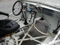
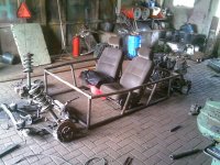

photo 1:

I spent about an hour walkign around, not knowing where to start, as i normally build trailers (built around 2 hot rolled steel frame beams) instead of buggies with an open cage construction.
Then i decided to start with the parts that allowed the most design freedom, which is the passenger cage, and later add the parts to mount both Volvo subframes, so i could better visualise where all the supports for the subframe mountings and spring mounts would go.
It turned out to be a good method, because within an hour or 2, i had what can be seen in photo 1.
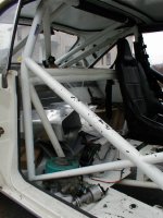
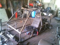

photo 2:

I used the hydraulic pipe bender to bend a roll bar over the spot where the seats would go. Unfortunately i had only 1 pipe die, which was for a 1" pipe, not for 1,5" so i pressed the pipe oval in the bend. To reduce the effect of making the pipe oval, i bent it in 3 or 4 places to make just 1 bend.
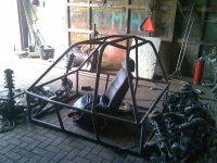
photo 3:

an extra hoop is added to the rollbar, and some pipes from the front part of the passenger cage to the rollbar are added.
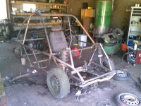
photo 4:

I've built the mounts for the front subframe, with steering housing. I had to bend the front quite a bit to work around the springs. I also had to chamfer off the front part of the passenger cage, because the front wheels couldnt sit there because they hit the lower front tube.
When i bolted some wheels on it, it really started to appeal.
several people that came around during the holiday, asked me when they could test drive it... ;)


At the rear, i'll be using the complete front wheel drive drivetrain at the back, just like Toyota used a Camry front wheel drive driveline in the back of the MR2 rear wheel drive sports car.
Photos will follow when i have time to continue.
 

Attachments

  • 31072007.jpg
    31072007.jpg
    533.4 KB · Views: 3,955
  • 31072007(001).jpg
    31072007(001).jpg
    301.3 KB · Views: 1,927
  • 31072007(002).jpg
    31072007(002).jpg
    286.5 KB · Views: 1,883
  • 04082007.jpg
    04082007.jpg
    283.8 KB · Views: 2,535
Last edited:
/ building a dirt buggy #2  
Looks pretty cool. Can't wait to watch this project come along :)
 
/ building a dirt buggy
  • Thread Starter
#3  
Yes, i cant wait either... But i have so many important things to do... ;)

I am wondering how well this buggy will handle, it has pretty much all the weight in the rear.... any of you drag racing experts, what's a reasonable weight distribution for a rear wheel drive ?

I think with the current setup it will take off on its rear wheels as soon as you step on the gas pedal... For safety i might have to add front ballast, but i dont want to compromise too much on the current power to weight ratio...
I think i'm going to put the battery up front, which puts about 25 kg (5%) of the weight to the front... I cannot put the fuel tank up front as well, because i didnt save an electrical fuel booster pump from the parts donors. The fuel flow must be gravity fed from a tank mounted above the engine.


Does anyone know how a glow fuse timer works, and how to re-wire it ?
Maybe i should just wire the glow fuses directly to a manual button so i can hold the button for 10 seconds before cranking it up, and forget about the complications of the standard contact lock in the steering column.

By the way, this buggy will probably keep its power steering system, because my friend (co-builder) lost control of 4 of his fingers on his right arm due to a car crash when he fell asleep behind the wheel, so he has only 1 hand to steer...
Because of his crash experience, i will weld some extra struts and trusses into the rollcage... ;)
 
/ building a dirt buggy #5  
Looks like a fun project. I really like the floor in your workshop!!!

I don't know anything about the vehicles your using, so it will be fun to follow your progress and see how it all comes together.

Thanks,
Eddie
 
/ building a dirt buggy #6  
So far, it looks good. Only thing I can add to your basic structure is to remind you that TRIANGLES are strong, boxes are not. Small triangles are stronger than large triangles. It is stronger to pull a tube than push a tube, but your weld is more stressed in tension than compression, plus it's usually not feasible given things like ground clearance. If force pushes a tube (for instance the upper spring mounts) have tubes direct that force into the main structure. See attached pics for examples of triangles transmitting force to main structure (main hoop of roll bar).

"Ideal" weight distribution would be 50/50 given your short wheel base & intended use.
 

Attachments

  • joesdart6.JPG
    joesdart6.JPG
    132.7 KB · Views: 1,463
  • joesdart7.JPG
    joesdart7.JPG
    111 KB · Views: 1,332
/ building a dirt buggy #7  
Renze said:
Yes, i cant wait either... But i have so many important things to do... ;)

Snip

By the way, this buggy will probably keep its power steering system, because my friend (co-builder) lost control of 4 of his fingers on his right arm due to a car crash when he fell asleep behind the wheel, so he has only 1 hand to steer...
Because of his crash experience, i will weld some extra struts and trusses into the rollcage... ;)

You might consider creating a glove typ. of the one Mel Kenyon, his Bro. and Father created for him after a horrific crash where he his fingers were burned off of his left hand.
Good luck
L*S

From : Mel Kenyon: The King of the Midgets
Miraculously Mel survived and after series of operations at the San Antonio Burn Center and a lengthy absence from auto racing, Mel returned to auto racing the next year missing virtually all of the fingers on his left hand. Together with his brother Don and his father Everett, they designed a special glove in which a rubber grommet was sewn into the palm. This was to fit over a stud on the steering wheel so that he could grab the wheel with his right hand and steer with the palm of his left hand.
 
/ building a dirt buggy
  • Thread Starter
#8  
Eddie,

the floor in my workshop are concrete pavers, sized 10x20x8 centimeter. This is a very common way to pave surfaces in Holland, all of our property is done this way. I dont know why, but Americans seem to pour concrete everywhere, and i havent seen a single paving brick when i was in Canada...
the main advantage of paver bricks is that you can re-pave when the dirt has settled over years, or get acces to the underground utility network under our streets, without hiring a concrete saw...


DBdartman,

i know about them triangles... i just need more 1 3/4" (42 mm) pipe to finish the rear end, and then 33mm (1 1/4" ??) pipe to make the triangles. Grinding a radius to every pipe to connect to the other is just way too much work, so i only do that for the main construction.
I dont want to ease the job by compressing the ends of the pipes either. I think i can weld the gaps between the radius of a 42mm pipe, and the open end of a 33mm pipe.
I had in mind to add several meters of pipes for various supports and extra bars, i'm not half done yet ;)

On the other hand, i only want the passenger cage to be stiff, not the front end as it should absorb the impact by crumbling, in case it might happen...


LeonS,

my friend isnt "missing" 4 of his fingers, he just cant use them anymore because a nerve was ripped loose in his shoulder when his arm slung forward at the moment he hit the tree... He can use his palm to steer, but not use both hands to grab and take over the steering wheel in a drifting slalom...


Does anyone have an estimate of the weight of a European 1.9 diesel (steel crankcase, aluminium head) with an aluminium transaxle ? I dont have scales that go higher than 120 kg, and neither a clue about what the rear end may weigh...

Sure 50/50 weight ratio would be ideal, but i am not intending to add 400 kg of ballast to the front to get to 50/50... is 45/55 acceptible, or does it get very tricky then ?
 
/ building a dirt buggy #9  
Renze, do you have a chop saw? Making a "fish-mouth" (to fit end of tube to side of tube) can be fast or slow, very precise or "close enough" depending on the result you want. When I worked in the fab shop I used a hole saw in an old milling machine to make fish-mouths if I wanted them tight. There are cutting jigs available (around $100-$200 USD) available that also use a hole saw. I have, after very little trial & error, learned to make reasonably tight fish-mouths with a chop saw & 4" or 4.5" (roughly 100 or 120mm) grinder. Once you figure it out, it should only take a couple minutes with the chop saw & grinder method. It's nearly impossible to use words to tell how to do it, but if you're interested I can take & post a few pictures showing how it's done. I built such roll bars from 1986 - 2000, so I know a thing or two about it. The car above I built for a friend. He's been drag racing it for almost 20 years now. It's heavy, at 2900 lbs (around 1400 kilos) but is over-built (safe!), fast, & consistent (9.0-9.1 seconds in the quarter mile at 148-149 MPH). Attached are a couple pics taken 2 years ago, above post pics were taken about 7 years ago.
 

Attachments

  • joedartleft.JPG
    joedartleft.JPG
    53.1 KB · Views: 1,023
  • joedartfront.JPG
    joedartfront.JPG
    59.6 KB · Views: 1,179
/ building a dirt buggy #10  
I would look at the vw sand/rail buggies. They do not have anything close to 50/50 balance. They do jumps fine. Steering may be light, but you can use independent rear brakes to help with understeer.
 
/ building a dirt buggy #11  
i have a tube bender but i know a guy that bent all his bends by packing the tube with sand.it seamed to reduce the kinks and oval"s...
 
/ building a dirt buggy
  • Thread Starter
#12  
Some more pics:

Photo 1 shows the pipe weld joints as i did in 90% of the joints:
I took off an edge at 45° with the angle grinder. After grinding it off, i had to touch it up with the bench grinder to get a good fit to the round pipe.

photo 2:

A photo from the drivers seat, you can see the Volvo subframe with a power steering rack and pinion housing, a powersteering pump on the ground, still connected with the hoses to prevent dirt from entering the system.
You can also see how the spring struts are connected to the frame. I need to put a connecting bridge inbetween them and solidify it by making angles.
The spring struts themself are bolted with 2 M8 bolts onto 2 angle irons.
I sawed a hole into the angle iron and then chopped off the angle iron in half with the band saw, so the result is 2 angle irons with a half radius.

photo 3 shows an overview picture of the buggy, front part on wheels, rear end on 2 bricks.
the original Volvo seat is placed on 3 plastic butcher's crates, at about the correct seat height.

When sitting in the seat, i dont know how it will feel, i gues topping 200 km/h with this thing will be a bit more scary than when i did it with the car this motor comes from....
Anyways, i dont need to go that fast, when the cops try to catch me in the bush, i will quickly disappear out of sight and then be unfindable because i know the local forest better than any copper.. :D
 

Attachments

  • 08082007(001).jpg
    08082007(001).jpg
    175.3 KB · Views: 953
  • 08082007(002).jpg
    08082007(002).jpg
    139.5 KB · Views: 816
  • 08082007.jpg
    08082007.jpg
    158.7 KB · Views: 865
/ building a dirt buggy #13  
Only thing that scares me is the bends you made with the wrong size shoes (VERY noticeable in your last pics). The kinks in the bend WILL be your weak point & WILL fold. A large X in the main hoop would be my first suggestion, but gussets at a 45° angle with 1-1/4" tube under those bends would be better than nothing. I would hate to hear that you put it on it's side & the cage folded over on you!

Your ties from the front to the main cage look good! Should allow some movement, plus in a hard hit should fold without too much distortion of the main cage.
 
/ building a dirt buggy #14  
A great thread and neat pics. I do have a concern about your battery placement. How do you intend to contain the acid if the battery gets ruptured?
 
/ building a dirt buggy
  • Thread Starter
#15  
dbdartman, yes i took that photo to illustrate the fishmouthing of the pipes, AND the deformation of the pipe in the bend, however i didnt mention it in the description.

I could correct the leg-to-leg distance of the rollbar by simply putting one end under my workbench and putting my 70 kg of body weight on it... I know that aint good, but i will at least weld 2 X-es into the structure: 1 directly behind the passenger cage, and one in the rear structure (i havent built that yet) that will run from the rear subframe mounts to the upper part of the rollcage. then i can extend the rigidity further forward by adding some crossbars in the`roof`
The ovaled pipes arent ideal, but i dont worry that much about them, sometimes, something turns "right" by going left 3 times ;)

About the ties from front to passenger cage, my guess is that in case of impact, the front Volvo subframe will be ripped of its four M12 bolts and will simply disappear underneath the buggy...

When thinking it over, i might have to have an arch in the pipes that run straight forward, so they will fold up instead of folding the front uprights of the passenger cage....

With some gussets i can put the weakest point a bit further away from the passenger cage, to achieve the crumble zone.
I'm not intending to crash it, but with my friends crash experience we just want to be prepared... My friend didnt drive fast or reckless, he simply fell asleep after a 12 hour night shift... You dont have to be reckless to get yourself in serious trouble, we both realise that very well now...


TLB user, my plan was to rivet some plastified sheet steel around the buggy, leftovers from the horse riding hall my brother built last year. It is featherlight and has a nice camouflage dark green colour.
The floor, and the front firewall i'll make of 18mm plywood. I have an original Volvo hood which with a little force, we can fold over the front part of the buggy.
I'll probably make a crate out of angle iron, which can accept some 60x40cm washed gravel patio stones as ballast.

It's thursday now, and today will be the last day that i'm working in my fathers sow barn, cutting up cages to turn them into hog raising sties.
My father turns 65 next year, but because the weeners are cheaper than the feed they eat, where meat hog prices are reasonable, he decided to stop a little earlier and raise the weeners in the old sow barn to get some money from those weeners.
With the foot and mouth disease in England, we can only move animals to the butcher, and not sell the 23-25kg weeners. (doing just 18 euro per weener) Because of this, i have to hurry up a little to make the hog raising barn ready, otherwise we run out of nursery stalls.

The point i was trying to make with the hogs and weener sideline talk, is that rebuilding the sow barn into a raising barn is a higher priority than the buggy, and that i hope to finish the stink work today and continue on the dirt buggy tomorrow... :)
 
Last edited:
/ building a dirt buggy
  • Thread Starter
#16  
O.k. guys, i could make a little progress yesterday, but it definately shows where it is going:

Photo 1

A side close-up of how the front wheel strut is connected to the frame. These are the parts that consume the most time, as there are no straight lines to work from and the pipes have to be bent in all kinds of directions to get them where i want them.


Photo 2:

When i welded the rear subframe mounting brackets to the lower rear pipe, the wheelbase turned out to be 2.55 meter. The wheelbase of the donor car was 2.50 meter. This way the rear end would stick out, making it all a bit out of proportion.
I decided to chamfer off the rear end of the cage about 20 centimeter, bringing the wheelbase back to 2.35 meter (or 92 and 1/2 inch)

Photo 3:

photo 3 shows the rear subframe lifted onto bricks and jack stands, with the front brackets bolted up but no supports to the rear subframe mounts.
when everything is aligned i can fit the pipes inbetween the given dimensions.
 

Attachments

  • 11082007(002).jpg
    11082007(002).jpg
    172.8 KB · Views: 826
  • 11082007(001).jpg
    11082007(001).jpg
    213.2 KB · Views: 650
  • 11082007.jpg
    11082007.jpg
    178.7 KB · Views: 679
/ building a dirt buggy
  • Thread Starter
#17  
/ building a dirt buggy #18  
performace over jumps have everything to do with

spring ratios

shocks.

to much front spring your launch nose high.

to much rear spring the back end launches up and you land hose heavy

shocks dont affect takeoff... just landing.
 
/ building a dirt buggy
  • Thread Starter
#19  
The car landed nose down every time. The weight distribution was somewhere between 51 and 53% front, i think. Now we've got the suspension in the buggy with half of its weight removed, it will be a bit stiff. because the engine is now in the rear, the weight ratio is totally different and i think i have to use front ballast to give the front end foothold to the ground, otherwise it will bounce around without any spring deflection.

When jumping a short bump as a ramp, shocks certainly have to do something with it.
 
/ building a dirt buggy
  • Thread Starter
#20  
Some more photos:

Friday night i worked in the workshop till 11, and i could spend a couple of hours on saturday.

Photo 1:

when i jumped on the front end, there was no spring deflection. all movement i got, was from a poorly inflated tire.
I put 4 Ford tractor front weights on the front, i guess its about a 150 kg. Then i could spring it about 2 inches when i used my body weight to jump on it.
I guess i need an oak strunk as front bumper annex ballast. ;)

photo 2:

A photo of the rear part of the frame, where the engine fits.


Photo 3:

rear view: With this shape and height, with sufficient fantasy it resembles a Volvo XC 90 SUV... :p
This is the most tricky part, because it needs to hold not just the spring struts but also clear 2 driveshafts, and hold 2 rubber motor mounts: The engine should also hang in the middle because the homokinetic joints of the driveshaft are going to jerk if it doesnt...
Just one advantage of the rear wheel drive set-up: Even with extreme spring travel, the angles of the homokinetic joints are reduced because the wheels dont have to make a steering angle anymore.
 

Attachments

  • 18082007(005).jpg
    18082007(005).jpg
    239.3 KB · Views: 730
  • 18082007(003).jpg
    18082007(003).jpg
    245.2 KB · Views: 589
  • 18082007(001).jpg
    18082007(001).jpg
    238.1 KB · Views: 656
 
Top