Bridge Crane designs and ideas...38' span

   / Bridge Crane designs and ideas...38' span
  • Thread Starter
#101  
Boy they sure dont make it easy.

I'll have to go through that and study everything tonight if I have some free time at work.

Without having the time to go through everything now, it appears the end result you gave solves for max deflection.

I dont think deflection is my concern. My limiting factor is bending stress in the beam. A taller beam with the same I4 sees more stress, but same deflection.

Keeping myself at 5:1 SF as far as stress is concerned, deflection is not a concern.

Does the same process apply for calculating stress of a double stacked beam?

We have solidworks at work. I am gonna see if there is anything in that program to play with as well
 
   / Bridge Crane designs and ideas...38' span #102  
Does the same process apply for calculating stress of a double stacked beam?

Actually, the stress is far simpler -- it's just a function of the bending moment and the beam's local I. In the middle of the beam it would be:

stress = (P * L * H) / (8 * I)

where P is the load, L is the beam length, H is the beam height, and I is the area moment. This will give the maximum tension or compression.

At any point along the beam, with x being the distance from the end, the stress would be:

stress{x} = (P * H *x) / (4 * I)

In the case of a beam that is stacked in the middle, there is a non-trivial transition of stresses where the stacking starts, and that is not something we can compute directly on paper. But you can bracket the problem.

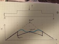
Going back to the example I sketched, I'd calculate the stress for the unstacked beam at both x=L/4 and x=L/2. The first instance is what the stress would be where the stacking starts. The second would be the max stress in the middle if there was no stacking. Let's call the second sigma-1-max on my sketch below.

Now calculate the stress for the stacked beam at x=L/4 and x=L/2. The first is what the stress would be at the stack section if we could miraculously transfer all stresses into the stack, and lets call it sigma-2-min. The second will be the max stress in the middle with stacking, sigma-2-max.

The attached sketch plots what the stress would look like. The actual heights and slopes depend on I1 and I2, but here I just assume I2 is higher so that the slope is less in the stacked section of the beam.

If stresses transferred into the stack perfectly, you'd get the jagged sawtooth profile with a discontinuity. But that won't happen -- initially the lower beam would continue carrying the load, so the stress would continue growing along the dashed line towards sigma-1-max. At some point, probably 1-2 beam heights from the start of the stack, the stresses will blend (blue curve) to the stress profile of the stacked beam. By the time you get to the center of the beam, the stack would be taking the full load over a good portion of the center of the beam. The shape of that transition is what would be hard to compute on paper, but if you could draw this plot with exact inputs for I1, I2, and the other data, you can probably get a good eyeball idea how it will look. That's what I would do, and I'd consider that an 85-90% confidence assesment.

IMG_6046.jpg
 
   / Bridge Crane designs and ideas...38' span #103  
Parallel axis theorem.....just the missing piece I was looking for.

Found this....nice video https://www.youtube.com/watch?v=WDdkdC1sFQQ

Working out the numbers for the following....

W12x65 beam
Wf = 12.000
Tf = .605
Tw = .390
Height = 12.1

I come up with Ix = 519 Pretty close. Beam is actually listed at 533 due to the radius I didnt account for. But proved to myself the formula works.

Adding a W6x12 beam underneath...
Wf = 4.00"
Tf = 0.280"
Tw = 0.230"
Height = 6.03"
Ix all by itself... 22.1

Stacking them I get Ix = 759. And in reality probably closer to 800 since I didnt account for the radius where web meets flange.

Dont really gain anything in the way of lifting capacity though.:thumbdown: If I use Bending stress as the ultimate limiting factor. Keeping it 5:1 for safety limits max stress to 7200psi. Adding height to the beam dont do any favors in that department since the beam height (or rather 1/2 the beam height c) is part of that equation.

But what it does do is decrease deflection by about 50%.

Results...single W12x65 beam, 38' span, 5k load in the middle....~6650psi stress, 0.634" deflection
Stacked beams same load and span.........................................~6800psi stress, 0.434" deflection

Just for fun I drew this up in my CAD program (Anvil 1000). I used a radius of .375 for large beam, .250 for small beam. It shows Ix = 793.8. The neutral axis is 7.49 down from top of large beam. Seems like the maximum stress is compression in the top beam. Since the neutral axis is moved down it sure seems like it would reduce the stress by adding the second beam underneath, and raise the load capacity.

I had 1 year of engineering in college long ago, so maybe I'm thinking of it wrong.
 
   / Bridge Crane designs and ideas...38' span
  • Thread Starter
#104  
I would have thought load capacity would increase also. And if I used the 793 i4 you figure....it might slightly.

But just the big beam by itself is 533. I thing given a really heavy beam with a really light beam is the issue.

Stress formula is simple enough. 12" beam/533i combo vs 18"/793 combo.

Hells a bunch with deflection though
 
   / Bridge Crane designs and ideas...38' span #105  
Are you using a stress formula that takes into account that the neutral axis is no longer in the center vertically after you add the second beam? There's one in Machinery's Handbook for a beam supported at both ends and load in the center.
 
   / Bridge Crane designs and ideas...38' span #106  
A w27X114 is a massive beam. I don't think LD needs something that massive. His beam calc already come out with less than 1" of deflection with a 5:1 safety factor.

1" deflection might as well be a roller coaster with the weight in question. You'll get it lifted, then it'll start fighting you to find the lowest point. Dangerous to say the least, and generally unacceptable in functional use without a servo controlled chain or gear drive on the axis that flexed that much = $$$$$.

I have a 20x24' bridge crane I built 7 years ago. I used S15 and S12 respectively: my 24' runway is supported at around 19' span with the S12s and my trolleys are 36" axle to axle so the bridge beam's load is distributed over a reasonable distance. I designed it with a max load of 2T and have moved 4,700# a few times, and it does flex with that much weight between the two S12's mid-span (pretty much a 1.25x test load scenario). It's rock solid with my 3,200# lathe on it. Most of what I use it for is well under 1,000#, but I wanted to be able to move my machines. Flying a surface grinder from one end of the shop to the other sure beats the Egyptian method!

The castellated beam option is probably the easiest to construct for the straightest rails, but perhaps a fabricated beam out of angle would get you the stiffness you need without breaking the bank? Remember every pound of crane counts against your load limit. My beams were all 840# each and cost me $3/lb at the time.

Tying the runways into your structure is another option that many over look. I was able to reduce my pillar costs significantly by gusseting them into the 2x6 stick framing at two points above the floor plates (3 total points of connection). All but one of the 4 pillars is supported by a corner of walls at 12" away from the vertical side. That last column is attached to 3 studs instead of two on either side of the 90 like the others. You don't necessarily need to attach it at the ground. If your roof can support it, you can suspend your runways and suspend your bridge below them. That'd get you to where you can use a lighter beam and keep the open floor.
 
   / Bridge Crane designs and ideas...38' span #107  
Btw, to eliminate my spongy performance at the max load, I could cap the rails with channel, but it's not a problem. The I's will fold over sideways before they sag vertically - that's what your modeling is lacking. Look at CM's data and offerings. They have a good chart, or did, on what size was needed for what span and what load with a 5:1 SF. I pretty much used it to cross-check my own calculations and found that they were plenty conservative enough while not over-building to an obscene cost of construction.

Here's one from Harrington: http://www.harringtonhoists.com/tech_support/edocs/EDOC 0367 rev02.pdf
 
   / Bridge Crane designs and ideas...38' span
  • Thread Starter
#108  
I am not going to tie it to the roof with the loads I am talking. And my rails are only gonna span 12' with 2 colums, and I have all those materials aready. So not not gonna save anything there. No way to get around needing a heavy beam for a 38' bridge span.

I will tie the side rails to the walls to help with lateral stability.

Using a W12x65 beam, I dont think I have any worries at all about the beam trying to fold over sideways (torsional buckling). S-beams or tall skinny beams, yes that is a real concern. And thats what the channel cap is for. The channel cap dont do much for deflection. But does tons for torsional buckling. Thats why you see them mostly on S-type beams like you have, because those beams are always tall and skinny.

Goal is to keep deflection to L/800 or better. Which is around 0.60" deflection. I dont think that is going to be an issue over a nearly 40' span
 
   / Bridge Crane designs and ideas...38' span #109  
We have solidworks at work. I am gonna see if there is anything in that program to play with as well

There is. Simulation Express........
It will only do parts, not assemblies. To do the beam stacking, you can get creative and make it work.
 
   / Bridge Crane designs and ideas...38' span #110  
I added a 1 x 4 solid bar to the bottom of the 6 x 4 beam and it raised the Ix of the assembly to 1218. Neutral axis 9.18 from top of 12" beam. More cost and more welding though.
 

Tractor & Equipment Auctions

2021 Dosko 337S-13HC Walk-Behind Stump Grinder (A49461)
2021 Dosko...
2015 MACK GU713 DAYCAB (A50854)
2015 MACK GU713...
2017-2023 Ford Super Duty 4x4 Pickup Truck Bed (A49461)
2017-2023 Ford...
2019 Bobcat E32i Mini Excavator (A50322)
2019 Bobcat E32i...
2018 FABRIQUE 20FT TRAILER (A51222)
2018 FABRIQUE 20FT...
3in Poly Pipe (A49461)
 
Top