Bridge Crane designs and ideas...38' span

   / Bridge Crane designs and ideas...38' span
  • Thread Starter
#91  
Your calculation for moment of inertia is lower than beam value, Because the beam flanges are slightly tapered. They are thicker near the web

These are W-type beams, not S-type, so the flanges are uniform thickness. Whats not accounted for is the radius where the web meets the flange.

I could find the radius and calculate that, but given the small amount I didnt feel it was worth the time to calculate. So just calculating it as square and using a 5:1SF....I might have a 5.1:1 SF when all said and done.

IOW, I am not concerned about the extra 10# I might be able to lift figuring in the radius.
 
   / Bridge Crane designs and ideas...38' span #92  
Rolling the beam in the mill induces a taper. S type is more severe than W, but both have the taper
 
   / Bridge Crane designs and ideas...38' span
  • Thread Starter
#93  
Rolling the beam in the mill induces a taper. S type is more severe than W, but both have the taper

I dont buy this.

I have 3 w-type beams on my rack.

W4x13
W6x12
W6x25 (I mis-spoke earlier. I was thinking this was a W8 but it isnt).

Of these 3 beams, measuring the flanges at the edge and near the web with micrometers, there isnt more than .003" in any of my measurements. Likely surface rust and mill scale variations.

What there is though, on the W4x13 beam is a 0.250" radius, W6x12 = 0.375" radius and the W6x25 is a 0.500" radius according to my gauges. The radius I believe is the ONLY thing that accounts for factoring a slightly lower Ix4 than published spec.

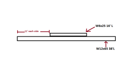
But its a moot point. IF anyone knows how to calculate stacked beams where they are only stacked in the center part of the beam for a given length I am all ears.

IE: like this...

stacked beams.png
 
   / Bridge Crane designs and ideas...38' span #94  
Ld
For the portion of the beam of the beam that is stacked. You would calculate loading based on that section. For the portion of single beam you would calculate based on the single beam strength.

If you have noticed bridges with reduced weight limits, this is how the reduced limit is calculated based on deterioration of the steel beams. Different beam section give different loadings
 
   / Bridge Crane designs and ideas...38' span
  • Thread Starter
#95  
Ld
For the portion of the beam of the beam that is stacked. You would calculate loading based on that section. For the portion of single beam you would calculate based on the single beam strength.

Example? Formulas?

All of the load assuming load at midspan, is going to be on the double stacked part.

Simple enough to calculate a double stack (now that I know how) prvided it is double stacked the entire length.

But what if the stacked section were 6' shorter? or 12' shorter? or 22' shorter like my examle? How does that effect total capacity.

Lots of MFG bridge cranes taper down at the ends. The extra mass is not needed there as on long spans, beam shear near the supports is rarely an issue, rather stress and deflection near the mid-point. But where the beam is narrower at the ends....how far can that be cheated out and still maintain full strength? and beyond that....how much increase or reduction in capacity at varying lengths of the second beam?
 
   / Bridge Crane designs and ideas...38' span #96  
For the 11 ft at each end calculate as single beam . For the middle calculate as double beam. You make load chart by combining the appropriate section of the charts from each beam section

You can make as many steps in the beam as you like. I have worked on old bridges with up to four different beam sections. For rating bridges, the beam was rated at the tenth points of each span typically.

Shear in beam is controlled by area of the area not its shape

What are you using to calculate stress and deflection. I ca explain easier after I look at the results?
 
Last edited:
   / Bridge Crane designs and ideas...38' span #97  
Ld
For the end 11 ft the beam will have the stress and deflections as if a single beam was loaded for the entire span. The middle will act as double beam for stress , but will have higher deflection. The deflection will be less than single beam though. I hope this helps explain load ratings.

Dave
 
   / Bridge Crane designs and ideas...38' span
  • Thread Starter
#98  
I made a spread sheet with all the W-types and all the S-type beams listed ranging from W10x12 up to W24x104. (I didnt list the super heavy 100+ PLF beams like a W14x600).

After I made the list, the only two beam specs needed was the c (distance from neutral axis to farthest fiber) and the i4.

After that I used the formulas for stress and deflection

Stress = cWl/4i
Deflection Wl^3/48Ei

Gave each beam a max capacity based on stress failure at 36ksi, and its deflection right beside that

Then gave a WLL assuming 5:1 SF so limiting stress to 7200psi, and listed its deflection beside that.

I also use Beamboy. But got tired of trying to remember all the beams and what they can handle. So I made the spread sheet. Gives the same basic info.

Also used a trial version of StruCalc 9.0. They have a pretty nice feature where you can input the beam, span, load, bracing, etc. Then choose a W12 beam and it will list the minimum requirements. So I did that with loads from 2k to 10k going up 1k at a time, and beams from 10" to 24" and made a chart. IE: Y axis shows loads from 2k, 3k, 4k,etc. X-axis is 10", 12", 14", etc beams.

That program matches up pretty well with the other ways I was calculating.

I am still lost on how to calculate the double beams. IF you have the time, could you walk me through an example. Even if its simplified. Like a 20' span and 10' beam in the middle to make things easy.
 
   / Bridge Crane designs and ideas...38' span #99  
Couple tricks can be used for what is basically a beam of variable cross-section.

One way (and this works in both directions) is to replace that double section of beam with something that has the same cross section (I) but assumes a much stronger material. You can use the ratio of I to determine the ratio of E, since they are side beside in most beam equations (i.e., if I is double, then replace with double E instead). However, you would still need to take into account the weakest E at some point, to make sure the actual stresses don't exceed it. This method is often used in reverse for composite beams, say an I-beam with wood lumber sistered in -- I'd replace the lumber with a smaller chunk of steel that has the same net E*I, but later check back to see that the resulting stresses are acceptable for the weaker material -- wood.

The other way is to break the calculation into sections, and label all the unknowns. Draw imaginary saw lines through the point where the single and stacked beam sections meet, and then replace the "connection" with lateral and vertical forces and a twisting moment -- basically, the forces and moments that were otherwise holding the beam together before you sawed it apart. The deflection at the end of the section of single beam will be the starting deflection for the section of double beam. You should be able to solve for all the forces and moments by doing sums in the horizontal and vertical directions, and sums of moments, for each of the sections you sawed apart.

I'll try to draw a sketch if I get a minute today, but hopefully the description makes sense.
 
   / Bridge Crane designs and ideas...38' span #100  
OK, here are a couple derivations that should help. First, for background, here is how a simple beam formula is derived using the differential equation for the elastic curve of a beam, which relates moment to curvature and material/shape properties:
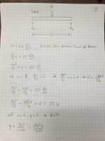
sb1.jpg sb2.jpg

That gives the well known deflection for a beam with simple supports and a point load in the middle.

Here's the same approach but for a beam that has a different area moment in the middle section. For convenience I assumed the beam is evenly spaced up in quarters, with the different section taking up the middle half.
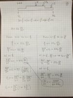
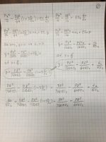
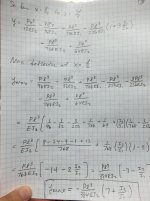
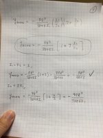
cb1.jpg cb2.jpg x3.jpg x4.jpg

I checked to make sure this more complex formula gave the simple result when the area moment was the same everywhere, and it does, which hopefully is a good check on my math. But it couldn't hurt to follow through and check my work. Really the hardest part of these derivations is not the Calculus, it's keeping track of all the math and fractions.

The basic gist of what I did in the second case was the same derivation, but breaking it down to apply to different sections of the beam. We can solve for unknown constants in the process by knowing deflection is zero at the end, that slope is zero in the middle at x=L/2, and that deflection and slope must be equal where the two different sections meet up at x=L/4. That lets us come up with equations for the whole beam.

Anyhow, using the result on page 4, you can plug in I1 (unstacked area moment) and I2 (stacked area moment) and get the deflection in the middle of the beam. Hope this helps!
 

Tractor & Equipment Auctions

2019 Ford Fusion SEL Sedan (A50324)
2019 Ford Fusion...
Mitsubishi FG35 Forklift - 8,000lb Lift Capacity, LP Gas (A51039)
Mitsubishi FG35...
DEWALT ROTARY HAMMER (A50854)
DEWALT ROTARY...
DOOSAN G25 GENERATOR (A50854)
DOOSAN G25...
Hyster H155XL Forklift (A48837)
Hyster H155XL...
Ford F-450 Utility Truck (A51039)
Ford F-450 Utility...
 
Top