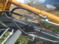
Thank you, ptsg! the regen function makes sense to me, but why would there be a relief valve on a single cylinder? Could you explain what you mean by self-leveling?
Self leveling, in that loader in particular, is that parallel linkage on top of the main arms. As you lift the loader, it will maintain the bucket at the same position from the ground all the way to the top. Same as you lower.
It's called "self leveling" but the name is somewhat misleading. It doesn't actually keep the bucket level all the times, it just keeps the bucket in the same position along the range of motion of the loader. Let's say you have the bucket curled all the way, as you lift the loader, it will keep that bucket in the same position.
This is also a great safety feature as it won't let you dump the load on top of the hood of the tractor. Lots of people got killed or injured that way with logs and hay bales.
The self leveling feature also reduces the need to do two functions at the same time by a lot. Without this feature, some tractors are very hard to do two functions at the same time due to either the control valve used or just not enough flow from the pump.
The relief valve has to be there because there certain positions that something has to give in order to prevent something from break and bend. So the relief valve just relieves the fluid.
Let's say you have the loader 1 meter in the air and you have the bucket dumped all the way to the stops. If you tried to lift the loader, the parallel linkage would try to push the cylinder further forward but since the bucket is already hitting the stops, it can't move. So the loader couldn't lift or it would damage something.
With this relief valve, it relieves the fluid from the extension port of the dump cylinders, so the loader can go back up. This relieved fluid is often sent to the retract side of the lift cylinders and then dumped back to the tank.
EDIT: The pressure on this relief valve is set lower than system pressure, so it can actually work as designed.
Hopefully my explanation makes sense. If not, let me know and maybe I can find some better wording.
I did find some manuals from Faucheux but none have an hydraulic schematic.