Hill Climbing Primer

   / Hill Climbing Primer #301  
Me thinks with you're levers at equilibrium and a torque applied at the pinion that is equal or greater than the tractor center mass to centreline of rear axle the front will continue to rise. You got a few more lever's there in the dynamics of things that don't diss appear in some gear case housing!:thumbsup:

I need help visualizing which levers are missing.

For the sake of illustration.
Consider a simple wheel tractor that is powered by hydraulic motors at each axle. There are many real world examples so constructed. More so in heavy equipment than in compact tractors.

Egon, will you describe the levers you see are important in such a system
 
   / Hill Climbing Primer #302  
I need help visualizing which levers are missing.

For the sake of illustration.
Consider a simple wheel tractor that is powered by hydraulic motors at each axle. There are many real world examples so constructed. More so in heavy equipment than in compact tractors

Egon, will you describe the levers you see are important in such a system
Well, for the hydraulic motors at each wheel it depends on the gearing setup.


In reality I see vectors not levers. Some mornings maybe an elephant or two!
For a regular tractor you got:
Load lever A variable dimension of vertical and horizontal force vectors that depend on the angle of pull depending on how the tractor is sitting.
Wheel radius lever
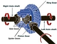
Ring gear diameter. This gear is fixed to the axle via another set of gears.
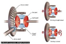
Pinion gear diameter. This one transfers the engine force to the ring gear and has the ability to rotate around the axle. You will note that the pinion centreline is fixed to the frame which is fixed to the axle housings which hold the axle bearings allowing the axle to rotate in the bearing. Stop the axle rotation and the tractor frame can rotate around the axle. Bearings help that out a lot!

And the distance from the center of mass to the rear axle. The force vectors exerted are functions of sine and cosine angles the tractor has to the horizontal.

There are even some spyder gears mixed in there.


image.jpg

image.jpg
 
Last edited:
   / Hill Climbing Primer #303  
Egon

Thank youi for posting these references Lot's of parts to consider, with most of them familiar to most tractor operators.

All those spinning gears can be confusing.

Your reply"
Well, for the hydraulic motors at each wheel it depends on the gearing setup. [end quote]

How about the important vectors for the simplest example?
No gears, just a wheel on a hydro motor, with the hydro motor bolted to the tractor chassis, and a couple of hoses that go back to the pump via a flow control valve. That should keep the forces simple. Maybe I would see which vectors turn the tractor over in that example;-)
I'm sure such a system would behave the same as a similar capacity driven axle at least in regard to pulling against a stuck load. Is that not true?
 
Last edited:
   / Hill Climbing Primer #304  
Well, for the hydraulic motors at each wheel it depends on the gearing setup.


In reality I see vectors not levers. Some mornings maybe an elephant or two!
For a regular tractor you got:
Load lever A variable dimension of vertical and horizontal force vectors that depend on the angle of pull depending on how the tractor is sitting.
Wheel radius lever
Ring gear diameter. This gear is fixed to the axle via another set of gears.
Pinion gear diameter. This one transfers the engine force to the ring gear and has the ability to rotate around the axle. You will note that the pinion centreline is fixed to the frame which is fixed to the axle housings which hold the axle bearings allowing the axle to rotate in the bearing. Stop the axle rotation and the tractor frame can rotate around the axle. Bearings help that out a lot!

And the distance from the center of mass to the rear axle. The force vectors exerted are functions of sine and cosine angles the tractor has to the horizontal.

There are even some spyder gears mixed in there.


View attachment 373706

View attachment 373707
Good. Absolutely, level ground for the simple case. [We can handle slopes too, but why complicate matters when we are stuck on the very principles of Mechanics.] Now pick out the stuf you need to know to simulate it identically. I know its hard - all those twirling gears and bearings. But when you understand it its easy. For an easy example see Post#291 and 297 where there is a small edit for clarity.
larry
 
   / Hill Climbing Primer #305  
Egon
Your reply"
Well, for the hydraulic motors at each wheel it depends on the gearing setup. [end quote]
How about the important vectors for the simplest example?
No gears, just a wheel on a hydro motor, with the hydro motor bolted to the tractor chassis, and a couple of hoses that go back to the pump via a flow control valve. That should keep the forces simple. Maybe I would see which vectors turn the tractor over in that example;-)
I'm sure such a system would behave the same as a similar capacity driven axle at least in regard to pulling against a stuck load. Is that not true?
... then wrap your head around the concept of using flex shaft drive to each wheel. Wouldnt take the torque but could be used as a scale model.
larry
 
   / Hill Climbing Primer #306  
Egon

Thank youi for posting these references Lot's of parts to consider, with most of them familiar to most tractor operators.

All those spinning gears can be confusing.

Your reply"
Well, for the hydraulic motors at each wheel it depends on the gearing setup. [end quote]

How about the important vectors for the simplest example?
No gears, just a wheel on a hydro motor, with the hydro motor bolted to the tractor chassis, and a couple of hoses that go back to the pump via a flow control valve. That should keep the forces simple. Maybe I would see which vectors turn the tractor over in that example;-)
I'm sure such a system would behave the same as a similar capacity driven axle at least in regard to pulling against a stuck load. Is that not true?

Just imagine the hydraulic motors connected to the pinion drive line. You will get all the vectors you need. In actuality there are a few more vectors including centripetal force, inertia and acceleration if'n you want to do it right. And speed of course!
 
   / Hill Climbing Primer #307  
Egon
Your reply"
Well, for the hydraulic motors at each wheel it depends on the gearing setup. [end quote]
... then wrap your head around the concept of using flex shaft drive to each wheel. Wouldnt take the torque but could be used as a scale model.
larry

Flex shaft; is that like Flex Time?

Would'nt mind building a RC canard drone though.
 
   / Hill Climbing Primer #308  
Egon

Thank youi for posting these references Lot's of parts to consider, with most of them familiar to most tractor operators.

All those spinning gears can be confusing.

Your reply"


Just imagine the hydraulic motors connected to the pinion drive line. You will get all the vectors you need. In actuality there are a few more vectors including centripetal force, inertia and acceleration if'n you want to do it right. And speed of course!

When I do that. I get right back to the same two levers, Both originating outside of the gearbox, at the axle. One, the length of the wheel/tire radius which is giving the "over turning" moment and resisted by the tractors weight which could be said to be located at the CoG. Let us call it the "wheel lever". Then there is a second lever from the business end of the draw bar that can be represented by a straight line drawn to the axle. Let us call that one the "load lever". This "load lever" just happens to have the the exact horizontal MAGNITUDE as the wheel lever's horizontal magnitude, for it is the wheel lever that gives the pull. The horizontal force is the one that would move the tractor over the ground, and pull a load along with it.

There are vertical force vectors associated with how the load is hitched (subject of many posts within this thread) They also can be translated to the axle center and would appear there as "torque" or a turning moment. For torque is no more than a force applied via a lever.

Which vectors am I not seeing? Again, just a hydraulic motor attached to the wheel hub and bolted to the tractor chassis.

Here is an example of the math I would use
http://www.markstivers.com/cartoons/Cartoons 2005/Stivers-1-1-05-Physics-of-c.gif


;-)
 
   / Hill Climbing Primer #310  
I concur. The tractor spinning like a wind mill around it's axle center would not happen.

And it appears you concur that in the beginning the front of the tractor will truly rise?

There is no doubt the front end will lift some, absolutely. Right around 45 degrees I think you would approach some steady state where the forces are going to balance. The stated conditions really don't exist because no tractor has infinite torque or traction. The load could certainly appear so. But even if the conditions did exist, it couldn't go all the way over because to do so would require forward motion of the hitch, requiring motion of the load and thereby breaking one of the initial conditions.

I'll ask again: can God make a rock so heavy he can't lift it? There is no answer to this question because it is a contrived situation.
 

Tractor & Equipment Auctions

2006 CATERPILLAR 320CL EXCAVATOR (A51242)
2006 CATERPILLAR...
2009 Lee-Boy 8510HD Conveyer Feed paver (A52128)
2009 Lee-Boy...
2024 Case IH Magnum 380AFS CVX Connect MFWD Tractor (A50657)
2024 Case IH...
2008 CATERPILLAR 430E BACKHOE (A51242)
2008 CATERPILLAR...
Toro Zero Turn Mower (A50324)
Toro Zero Turn...
2017 NISSAN NV200 VAN (A51406)
2017 NISSAN NV200...
 
Top