muddstopper
Veteran Member
Ok, I will admit, I am not the best hydraulic engineer. I have just enough sense to ask for advise. I just need opinions and suggestions on my proposed hydraulic setup. I was going to try and draw it out in Autocad, but the software I downloaded is buggy and wont display the symbols correctly. Anyways, here is what I have in mind.
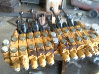
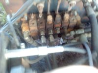
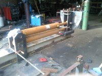
First off, saw motor is a 1.3 cuin Proclain axial piston motor, and splitter cylinders are twin 4.5X2.5X30in stroke. Engine 190hp diesel. I have 2 sets of stacked vavles, 10 spool and 8 spools, all spools have own reliefs. Rated for 25gpm. I have a v70 parker, spring centered, lever and air actuated. Plan on using foot pedal to operate. Looking for single spool valve with PB for saw motor. Must be rated for at least 30gpm.
I have been writing my thoughts down so this is just a copy and paste of me talking to myself. Sometimes I even answer myself, and sometimes the answer is even correct. Oh well
Processor Circuits/Functions
Current plans are for 3 separate pumps I am labeling these pumps as P1,P2, and P3. If i decide to add another pump, it will be considered P4.
Saw motor 33gpm flow P2 pump
Splitter cyl 42gpm flow P1 pump
P1 and P2 pumps will combine to provide 75gpm for splitting cylinders
14gpm, P3 pump
This pump will provide flow for all other circuits
Saw cyl
log clamp cyl
Log feed conveyor motor
wedge lift cyl
Out feed conveyor motor
Live deck motor
Deck lift cyl
Knuckle Boom Circuits/Functions
Since all previous listed functions will not be required while operating Knuckle boom, the P3 pump will be used to supply power
Right stabilizer cyl
Left stabilizer cyl
Mast rotation Motor
Root boom cyl
Dipper boom cyl
Grapple rotator motor (Valby R3)
Grapple clamp cyl
There is the possibility that I might make the outfeed conveyor to fold up for transport as well as swing side to side. For fold up, Scropion style, I think it would take two extra cylinders. One to raise the conveyor and the other to make it fold. I am thinking one control valve and using sequence valves so that the conveyor folds first and then raises and then lowers before it unfolds. Have to think about this, it might just be easier to use to seperate CV's. I guess it just depends on how may extra spools I have in my stacked valves. One cyl, one CV,extra if I decide to add swing.
Also, Not entirely sure I will use or need a fold up log deck for log storage, I should have about 4 ft of live deck and the knuckle boom will be mounted to the machine, so???, is the extra lenght of the live deck worth the trouble.
Advantage of a longer deck is you can load a bunch of logs for processing so you dont have to stop and reload logs as often.
Disadvantage, Cost more to build, and in the folded position it would be upright making machine height higher . Would also take up space needed for knuckle boom storage during transport.
I think the best way to figure out what valves I need is to just do them one function at a time. Since the saw and splitting circuit will use a combination of two differnt pumps, I will start there. After I write this out, I will try and draw up the schematics using proper symbols. Autocad software buggy, so this might take a while.
Starting with the saw, P2 pump makes 33gpm. flow will go to valve with relief between valve and pump. (Relief Internal in CV). SCV activated fluid goes from SCV to Motor and then to Tank. Valve in center postion, flow will go to PB and continue to CKV before combining with P1 pump flow. CKV is to prevent P1 pump flow from running backwards to saw motor.
Considering also adding a unloading valve with check valve bypass in the event P1 pressure rises above P2 pump relief setting which would cause P2 pump to dump over relief instead of going thru splitter valve. A unloading valve would allow oil to flow back to tank unrestricted instead of flowing thru relief valve. This would also make the P2 pump act as a high/low pump. Making the splitter act like it had a two stage pump instead of 2 seperate pumps.
P1 pump flow combines with P2 flow at tee and then to the in port of Splitter control valve with internal relief. Splitter control Valve In center position flows to tank. When activated it would extend or retract twin splitting cylinders. The twin cylinders are connected together in parallel.
I think this completes the splitter and saw circuits. All other circuits will be using the 14gpm P3 pump.
To complete the sawing of a log, I need to address the conveyor to advance the log as well as the clamping and lowering of the saw bar. Since this operation would be thru stacked valve, It should be as simple as activating the corresponding control lever and push and pull. Not so fast!! While this will work just fine for the conveyor. I am going to be dealing with different flow requirements as well as pressure requirements for the log clamp and saw cyl. Saw cyl needs to raise and lower in a controlled manner and pressures also need to be pretty low.
Recommended down force on saw cyl is less that 100psi pressure at mid saw bar. (Oregon recommends 60lbs force at mid bar).Log clamp pressure can be system pressure. I am thinking this is going to require more valves to make it work. My Ideal is to use a sequence valve off the log clamp cyl to activate the saw cyl. This way the clamp would see a set pressure to hold log in place, before the saw cyl moves. Still ,I dont think this will work because the saw cyl would also see full flow and pressure making it to fast and apply to much force. I can use a couple of flow controls to meter in and meter out flow to control speed, but then I still have to much pressure. To control pressure what about using a pressure reducing valve before the flow control valves. Thats a lot of plumbing for one cyl. Got to be a better way.
Advantage of using seperate flow control, sequence valve and pressure reducing valve. It allows wide range of adjustments to control both speed and force.
Disadvantage, Lots of valves and hoses to buy $$$, and very cluttered once installed. will have to see if possible to buy a all in one valve to perform all these functions. All in one valve will probably be cheaper than buying several seperate valves.
Next operation is where I might have to add an additional pump (P4) and that is the out feed conveyor. Conveyor needs to run continuous while sawing and splitting. If I pull fluid off the same pump as I am using to run the other conveyor as well as the log clamp and saw cyl, the outfeed conveyor will see start and stops. The outfeed conveyor and other splitting functions wont be running if I am running the knuckle boom. I have a few choices to make the out feed run all the time, I can add a divider valve before the clamp, sawbar and log feed and just dedicate a set amount of oil for that conveyor. I can add another small pump or I can pull some fluid off the splitter circuit as that valve is also PB. Not sure how I would get flows down to 4-5gpm from a 75gpm circuit, but I bet it would be costly.
Not a lot to discuss about the knuckle boom, except for adding a brake valve to the mast swing motor. While I could probably get by without the brake valve, I dont want the mast to be floating around uncontrolled if the machine isnt perfectly level.
I know I am crazy, but give me your suggestions and thoughts on making this system work.


