Tell us something we don’t know.

   / Tell us something we don’t know. #7,841  
But for the fact a dB is not a unit, it is a logarithmic multiplier. "80 dB" has no amplitude, no size. It is saying something is 80 dB stronger than something else but isn't saying what it is stronger than.

For sound we use dBA to signify it is using a scale arbitrarily defined as "A", and sadly A and acoustic use the same letter. But there is also a B acoustic scale.

What is an A-weighted decibel (dBA or dB(A))?

In radio terms we use dBm and dBV a lot. 0 dBm is 1 microvolt. 0 dBV is 1 Volt.
True, except oddly... dBm. Of course it's dB's over 1 mW, but nobody writes or says "dBmW", as they do with dBV or dBW. I'm as guilty as the rest, it's a convention I use many times per day, but I always thought it odd.

It's also odd that we specify power of enormous 10,000 watt amplifiers using milliwatts, as in 10 kW = 70 dBm. Might as well measure the distance from here to the moon in millimeters! :D
 
   / Tell us something we don’t know. #7,842  
I don’t know where MW gets their info from. I think they make it up. If it was true, why wouldn’t it be deciBell?
I think in some older Bell Labs white papers, it was, at least by a few select authors. I'm pretty sure I've seen it written that way in some of the old IRE (pre-dates IEEE) journals.

But I always thought the name was paying homage to the company (Bell Labs), not the man (Alex).
 
   / Tell us something we don’t know. #7,843  
I guess since we're on the subject of signals and power, here's another few things most might not know:

1. You are taught you need a return path for current to close a circuit. In other words, current flow from one terminal of a battery, thru the load (eg. lightbulb), and then returning to the opposite terminal of the battery through another wire. Closed circuit, so to speak. But it's actually possible to send electrical power down a tube or a square duct, like running water in a pipe, when the frequency is sufficiently high to shrink the wavelength below about 2 pipe diameters or duct widths. In simplest terms, this works because the voltage on one side of the duct or pipe is different than the other, due to the very short wavelength, and so even though connected by the circumference of the tube or duct, opposite walls of the duct act as separate wires with reverse current flow. There is a lower cutoff frequency to this behavior, but no upper cutoff, you just get more and more modes of propagation as frequency increases and wavelength shrinks, for a given tube size.

2. Energy is reflected from loads, any time a circuit is electrically long enough to be some noticeable fraction of a wavelength. This problem was first noticed by telegraphers, as they were the first to run AC signals over very long distances in the 1800's, and so the original equations describing this behavior are still called "telegraphers equations". Power utilities deal with this problem everyday, as although they're only running 60 Hz (3156 mile wavelengths), their wires are very long. The key to minimizing reflection is to match the impedance of the load to the impedance of the source, maximizing the amount of power absorbed at the load. In the most simplistic terms, you can think of this as not trying to generate more power than is being called for by the load.

3. Taking from item 2 above, an antenna is nothing more than an impedance matching device between free space (376 ohms) and your transmitter or receiver (classically 300 or 75 ohms). Create a good impedance matching transformer between the two, and you will have good antenna efficiency.
 
   / Tell us something we don’t know. #7,847  
OK, I think the subject matter has changed from "Things I don't know" to "This is WAY over my head!!!" :D

Carry on.
We all work in professions that are way over the heads of the general public. Hell, some here are farmers, and know way more about everything from GMO's to crop rotation to animal husbandry, than I will ever understand. Heck, I didn't fully understand how chickens and eggs worked, until I got me some ten years ago. :D
 
   / Tell us something we don’t know. #7,848  
Heck, I didn't fully understand how chickens and eggs worked, until I got me some ten years ago. :D
egg.jpeg

:)

Bruce
 
   / Tell us something we don’t know. #7,849  
I guess since we're on the subject of signals and power, here's another few things most might not know:

1. You are taught you need a return path for current to close a circuit. In other words, current flow from one terminal of a battery, thru the load (eg. lightbulb), and then returning to the opposite terminal of the battery through another wire. Closed circuit, so to speak. But it's actually possible to send electrical power down a tube or a square duct, like running water in a pipe, when the frequency is sufficiently high to shrink the wavelength below about 2 pipe diameters or duct widths. In simplest terms, this works because the voltage on one side of the duct or pipe is different than the other, due to the very short wavelength, and so even though connected by the circumference of the tube or duct, opposite walls of the duct act as separate wires with reverse current flow. There is a lower cutoff frequency to this behavior, but no upper cutoff, you just get more and more modes of propagation as frequency increases and wavelength shrinks, for a given tube size.

2. Energy is reflected from loads, any time a circuit is electrically long enough to be some noticeable fraction of a wavelength. This problem was first noticed by telegraphers, as they were the first to run AC signals over very long distances in the 1800's, and so the original equations describing this behavior are still called "telegraphers equations". Power utilities deal with this problem everyday, as although they're only running 60 Hz (3156 mile wavelengths), their wires are very long. The key to minimizing reflection is to match the impedance of the load to the impedance of the source, maximizing the amount of power absorbed at the load. In the most simplistic terms, you can think of this as not trying to generate more power than is being called for by the load.

3. Taking from item 2 above, an antenna is nothing more than an impedance matching device between free space (376 ohms) and your transmitter or receiver (classically 300 or 75 ohms). Create a good impedance matching transformer between the two, and you will have good antenna efficiency.
I'm thinking about a microwave oven, how it cooks with a magnetron through an antenna.
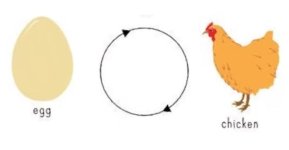
Here...this explains it easier than I can and tonight we had chicken and eggs heated in one, I'm not sure which came first though.
2024_03_12_22.22.57.jpg
 
 
Top