rswyan
Super Star Member
- Joined
- May 12, 2004
- Messages
- 13,455
- Location
- Northeast Ohio
- Tractor
- Kubota B2910, Cub Cadet Pro Z 154S, Simplicity 18 CFC, Cub Cadet 782
</font><font color="blue" class="small">( I thought these units came with the necessary connections to run all these attachments. )</font>
The attachments for the most part should come with hoses and hydraulic quick disconnect fittings, but the remote valves on the tractor would not be included.
</font><font color="blue" class="small">( If not, I really need to consider this issue when I make my purchase, new OR used. )</font>
Yup.
</font><font color="blue" class="small">( I will eventually need a BH (after I buy a friggn' tractor) and I assumed that it was self contained and ran off a PTO. )</font>
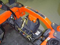
It could be that way - or not - depending on the specific backhoe brand and model. My BL4690B backhoe for my B2910 came with a PTO pump as part of the kit. On the otherhand the BH90 for larger tractors probably doesn't (runs off remotes) It just depends.
</font><font color="blue" class="small">( If these remote hydraulics are so expensive, either dealer installed when new or aftermarket, it really is a big issue... )</font>
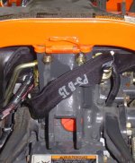
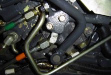
If you negociate remotes (parts & install) into the initial purchase you may be able to get a deal as part of the package. Otherwise going with an aftermarket/3rd party setup may save you considerable coin. I've spent around $350 or $400 on a 3 spool valve and fittings adding remotes to my B2910. The same setup using Kubota parts would have probably cost 3x that amount for the parts alone at full ticket.
The attachments for the most part should come with hoses and hydraulic quick disconnect fittings, but the remote valves on the tractor would not be included.
</font><font color="blue" class="small">( If not, I really need to consider this issue when I make my purchase, new OR used. )</font>
Yup.
</font><font color="blue" class="small">( I will eventually need a BH (after I buy a friggn' tractor) and I assumed that it was self contained and ran off a PTO. )</font>
It could be that way - or not - depending on the specific backhoe brand and model. My BL4690B backhoe for my B2910 came with a PTO pump as part of the kit. On the otherhand the BH90 for larger tractors probably doesn't (runs off remotes) It just depends.
</font><font color="blue" class="small">( If these remote hydraulics are so expensive, either dealer installed when new or aftermarket, it really is a big issue... )</font>
If you negociate remotes (parts & install) into the initial purchase you may be able to get a deal as part of the package. Otherwise going with an aftermarket/3rd party setup may save you considerable coin. I've spent around $350 or $400 on a 3 spool valve and fittings adding remotes to my B2910. The same setup using Kubota parts would have probably cost 3x that amount for the parts alone at full ticket.