Need Help With Hole Spacing On 3-point Stabilizers Please.

/ Need Help With Hole Spacing On 3-point Stabilizers Please. #21  
I know on the Kubota telescoping stabilizers, the swivel joint prevents the stabilizer from acting in compression. So only one side at a time is handling the load, when in tension.
 
/ Need Help With Hole Spacing On 3-point Stabilizers Please. #22  
Richard--I'm wondering about the necessity of having both stabilizers "locked in". Consider that, on a turnbuckle stabilizer system, only one of the lift arms at a time is carrying the side load. That would be the side in tension as the turnbuckle is non-functional in compression.

I'm not saying it'a necessity necssarily. Just saying the strength of the system is diminished. And then the structural strength of each stabilizer alone comes into play. :)
 
/ Need Help With Hole Spacing On 3-point Stabilizers Please. #23  
I know on the Kubota telescoping stabilizers, the swivel joint prevents the stabilizer from acting in compression. So only one side at a time is handling the load, when in tension.

Yes, design increases or decreases this issue. What's most important is minimizing the distance of the slack. The farther the load is allowed to swing before being stopped the more force is placed on the single stabilizer that stops it.
 
/ Need Help With Hole Spacing On 3-point Stabilizers Please. #24  
You do not want any looseness. That allows the implements to bang one way or the other and do some damage. I broke 2 parts of the lift assembly on my 4010 and bend the lift pin that holds the bottom lift arms when I left the turnbuckles a little bit loose.

I gave up using those little pins to secure the turnbuckles and just use tension cords. That way, you can get them tight and don't have to give up anything to get the little pins into place.
 
/ Need Help With Hole Spacing On 3-point Stabilizers Please. #25  
I was always taught to leave at least a little slack in the stabilizers, because over the range of motion of the lift arms, the distance along the stabilizer will vary (ultimately depends on the linkage layout compared to the arc of the lift arms). If you make the stabilizers perfectly snug at one position, they could bind when the lift arms move to another position. The behavior even changes depending on the width of the implement and how it spaces the lift arms. Basically, anything that affects the two relative arcs that the stabilizers and lift arms make when the lift arms swing through their range will play into this.

You want at least a teeny little slop in the 3-pt linkage over the whole range of motion. Doesn't matter where it comes from, but be careful snugging the stabilizers down too much as then you shift the need for slop to the ball ends of the lift arms and the pins on the implement. What I do, after hooking up an implement, is move it to extremes and make sure it still has a little jiggle.
 
/ Need Help With Hole Spacing On 3-point Stabilizers Please.
  • Thread Starter
#26  
I've noticed that working on sidehills can produce a lot of stress on the stabilizers. Pulling an implement in the ground and then raising it with the tractor tilted tends to whip the tractor front end sideways a bit.
 
/ Need Help With Hole Spacing On 3-point Stabilizers Please. #27  
I was always taught to leave at least a little slack in the stabilizers, because over the range of motion of the lift arms, the distance along the stabilizer will vary (ultimately depends on the linkage layout compared to the arc of the lift arms). If you make the stabilizers perfectly snug at one position, they could bind when the lift arms move to another position. The behavior even changes depending on the width of the implement and how it spaces the lift arms. Basically, anything that affects the two relative arcs that the stabilizers and lift arms make when the lift arms swing through their range will play into this.

You want at least a teeny little slop in the 3-pt linkage over the whole range of motion. Doesn't matter where it comes from, but be careful snugging the stabilizers down too much as then you shift the need for slop to the ball ends of the lift arms and the pins on the implement. What I do, after hooking up an implement, is move it to extremes and make sure it still has a little jiggle.

I think that's exactly right. The 3pt geometry isn't exact, so pinning it tightly runs the risk of binding/overloading something, especially over the full range of raising & lowering the implement. A little slack allows all the bits & pieces in the load path to adapt without developing too much stress. Keeping the slack low also minimizes the momentum that the implement can develop before the stabilizer checks its motion.
 
/ Need Help With Hole Spacing On 3-point Stabilizers Please. #28  
I'm in the same boat (needing to replace one or both garbage-designed threaded turnbuckles with either another one or set of garbage-designed threaded turnbuckles or a cobbled together telescoping version) and wondering what the ultimate outcome of this stabilizer fabrication project was.

So, npalen, what did you end up doing? Did you suck it up and just spend money on another set of crappy OEM threaded turnbuckles or did you instead fabricate your own telescoping version (perhaps along with increasing the effective axle length with the use of spacers an approach I fond referenced in another set of comments)? Photos please, if possible (or it didn't happen ;)).

In summation, it appears like the limiting factors are a) how short the stabilizers need to be (a factor of a given implement and, in the case of implements featuring wide attachment widths, how wide the lower arms need to be positioned to fit said implement) given the available real estate and b) the short length of the rear axle which creates the narrow stance of the tractor and which creates the limited real estate issue to begin with.

In my case, the widest the lower arms (of the 3-point hitch) - Kubota calls them each a "lower link" (67800-71214) need to be positioned is for a "Bush Hog"-brand rear blade (which I typical use for maintaining a gravel driveway and for plowing snow in the winter in conjunction with a clip-on snow plow that attaches to the front bucket) and which has an effective "attachment width" of about 32-inches. I only own two other implements for the three point hitch: a Bush Hog-brand "Squealer" and a tow hitch triangle (the latter of which I don't think I've ever used). The "Squealer" has a narrower attachment width of about 28", neccesitating that the stabilizers be lengthened (to faciltate attachment). IOW the wider the implement's "attachment width", the shorter the stabilizers need to be adjusted (and, conversely, the narrower the attachement width, the longer the stabilizers need to be adjusted).

As was pointed out earlier, the stock OEM stabilizers are, in their shortest configuration, only about 9-1/2" long and, I might add, only offer maybe an inch of two of travel. Said another way, in their longest configuration, they are only about 11" long (Note: I don't have a spare stabilizer in my hand - the only two I own are currently mounted on the tractor - so I can't give a perfect measurement; I'm just estimating here. But the point is that, compared to the telescoping stabilizers for the L-series, which appear to be really long by comparison (judging from this video:


...and which appear to offer many more inches of total adjustment, any stabilizer fitted to a B9200 needs to be very diminutive in length, thus limiting the options.

That said, I'm considering the option of modifying a set of the telescoping stabilizers (OEM or after-market - whichever model/version/iteration makes the most sense in terms of their stock length and design) - essentially cutting a set down in length - just so I can avoid having to throw good money after bad by buying another of the dreaded threaded-style stabilizers. Truth be known - I only currently need one stabilizer or, actually, part of one stabilizer - the male threads are shot on the 67830-71820-end (and by the time I've spent ~$60 to replace that component I might as well spend twice as much on an entirely new stabilizer 67830-71500) but the aftermarket telescoping stabilizer kits are ~$140 for a set of two so that's what has me exploring the idea of modification (along with being sick and tired of fighting with the threaded turnbuckles to begin with).

Hoping we can continue this thread and bring it to some kind of resolution.
 
Last edited:
/ Need Help With Hole Spacing On 3-point Stabilizers Please. #29  
After some thought I don't see why, at least at first glance, why I can't mount stabilizers inboard of the two lower arms of the three point hitch.

Here's an example of inboard mounting of turnbuckle-style stabilizers on what I believe is a model of TYM tractor (at least the dreaded turnbuckles are easier to get to/easier to access in this location):

142878386_418822432723462_6710332668218962799_n.jpg
 
Last edited:
/ Need Help With Hole Spacing On 3-point Stabilizers Please. #30  
And here's what I believe is a Kubota BX with telescoping stabilizers mounted inboard of the two lower arms. As you can see some allowance is made to clear the area where the upper arm connects to the lower arms.
81t5b21i+IL._SL1500_.jpg
 
Last edited:
/ Need Help With Hole Spacing On 3-point Stabilizers Please. #31  
If you use two different hole spacings,,
you will be able to get adjustments of far less than 1/4" per pin move.

Example (I ain't saying this is right)
On the exterior part, use 1" spacing
On the interior part, use 3/4" spacing.
Adjust to where you want it, then select the holes that happen to line up!!👍

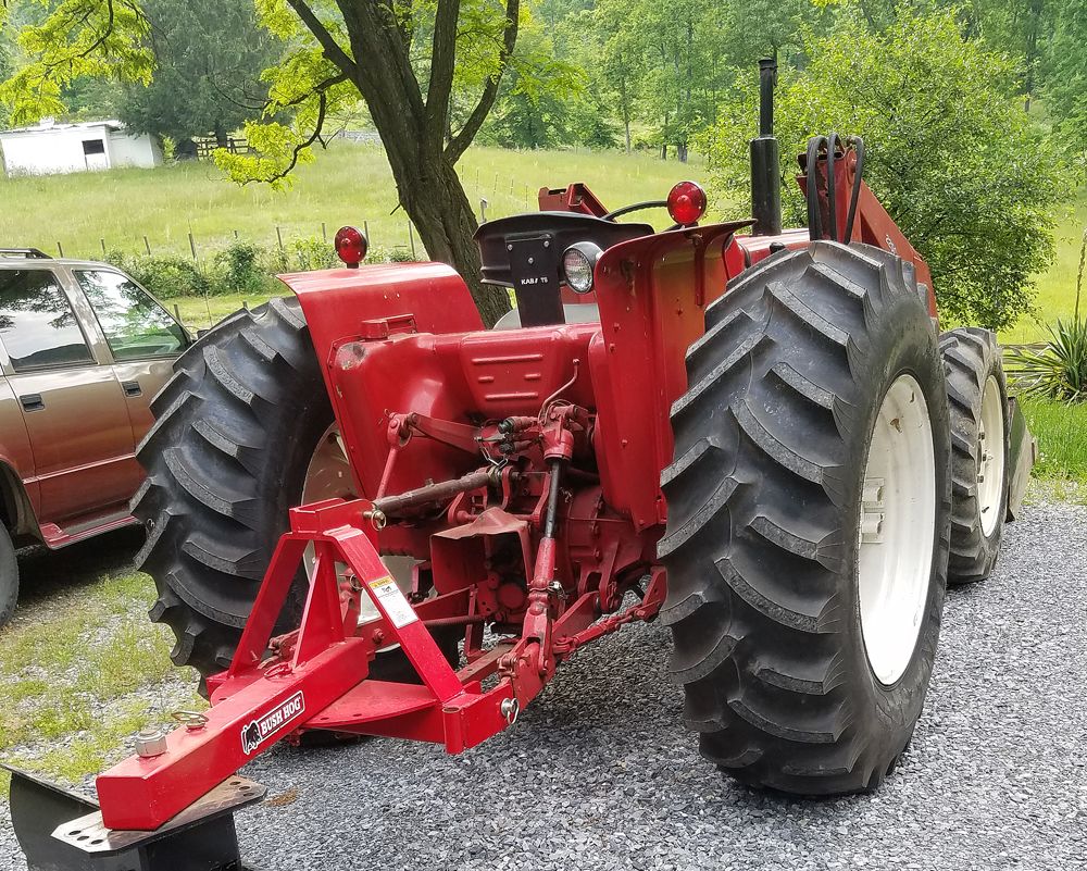
I have had my tractor since 1995,, I have never adjusted them
so I could care less if they were welded.

Right%20Rear_zpswiul2rok.jpg


I doubt they have been moved in the 35+ years life of the tractor,,
at least, they do not look to have ever been adjusted,,,

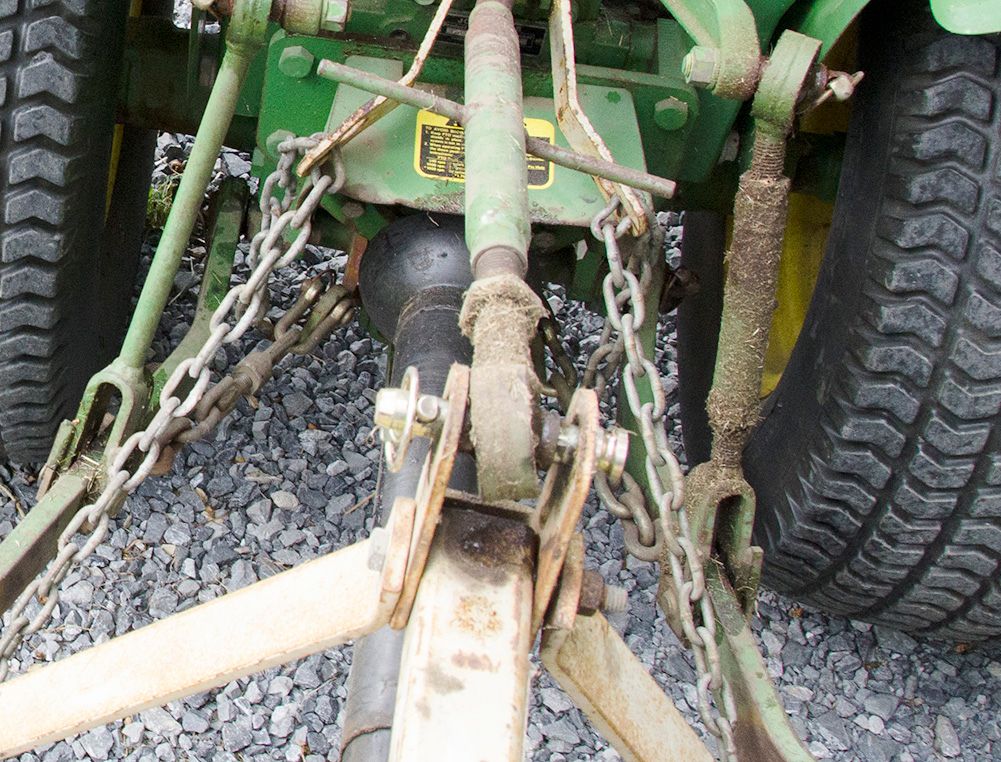
Below is probably the worst system EVER devised,,
inside the arms, turnbuckle chains.

650-4_zpszyu3rols.jpg


A chain has to be un-pinned, and removed,,, to remove an attachment,,
or, the arms must be left VERY loose,,, :confused2:
Vernier hole spacing.
Google Search
 
/ Need Help With Hole Spacing On 3-point Stabilizers Please. #32  
And here are some photos of my B9200 HST 4WD showing the existing arrangement (yes, there are some non OEM components currently in use - the shiny nut and bolt in place of the stock pin and split pin) as well as the location of unused mounting holes (circled in red - apologies for the yellow debris that's lodged in the middle of the three holes beneath the PTO, I didn't notice it while taking the photo) that could potentially be used for mounting telescoping stabilizers inboard of the lower arms as well as a simple depiction (a crude red line) showing approximately where I believe a telescoping stabilizer could be spanned. I also include a cropped image (blurry) showing a close up of the three mounting holes beneath the PTO).
Stock_compressed.jpg
Untitled_annotated_compressed.jpg
B9200compressed.jpg
B9200_1compressed.jpg
 
/ Need Help With Hole Spacing On 3-point Stabilizers Please. #33  
FWIW the distance between the left-most mounting hole beneath the PTO and the aft mounting hole in the left lower arm is 17", ample space for a lengthy-enough telescoping stabilizer.

Alternatively, is the stabilizers were mounted in a crisscross manner (so, left-most mounting hole beneath the PTO to the aft mounting hole in the right lower arm and right-most mounting hole beneath the PTO connected to the aft mounting hole in the left lower arm) - not sure if this would be advisable given the potential conflict with a drive shaft mounted to the PTO, but perhaps it's an option - then the distance between the mounting holes approaches 20" - more than enough space to accomodate telescoping-style stabilizers.
 
/ Need Help With Hole Spacing On 3-point Stabilizers Please. #34  
OK, I've seen the error of my ways. In all my fantasizing I failed to comprehend the nature of the relationship between the point in space in which a three point hitch's lower arm pivots relative to where it's attached to the tractor (so the "tractor end", as opposed to the "implement end") and the point in space where the tractor-end of a stabilizer pivots.

The reality is that these two points must be either exactly the same (of course this can't be since the two ends can't occupy the same space) or to the immediate left or right of each other. The respective points cannot vary from each other either fore and aft or up and down since any difference in either if these planes would create the catastrophic situation whereby the distance between the two mounting locations (for the implement-end and tractor end of the stabilizer) would shorten or lengthen (increase or decrease) as the implement was raised and lowered. This is a problem because once the length of the stabilizer is set, which is an essential step when attaching a given implement), it cannot change (the stabilizer is not spring loaded so its length remains fixed once it's length is set). Movement of those two points in space either left or right is OK since this differentiation doesn't result in the effective lengthening and shortening of the stabilizer - the effective length remains constant.

In the case of the layout of the B9200 there simply isn't the option of locating the tractor-ends of the stabilizers inboard of where the lower arms connect - the latter are tight up against the various castings that comprises the rear end of the tractor. Which is why the stabilizers are located outboard which, along with the short rear axle, end up severely limiting the placement options of the stabilizers.

All of which is a complicated way of saying that the only method for utilizing telescoping stabilizers on a B9200 is to first add wheel spacers (to increase the effective length of the rear axle) which will create enough space between the rear wheels to permit sufficiently long-enough telescoping stabilizers to be mounted outboard of the lower arms of the three point hitch. I say "sufficiently long-enough" because trying to fabricate teeny tiny short telescoping stabilizers (as direct replacements for the teeny tiny short turnbuckles) will result in two stabilizers which aren't fit for purpose. Their diminutive length (a limitation of the distance between the stock mounting locations) will not allow for sufficient adjustability - no matter how close together the pin holes are drilled.

What I've learned (thanks to some correspondence with Mark at Stabilworks) is that telescoping-style stabilizers need to be of a sufficient length to allow for enough variation via the fixed number of pin positions (in contrast to a threaded turnbuckle-style stabilizer, they are not infinitely adjustable) and one that's ~9-12" in its shortest configuration and ~11" in it's longest just won't allow for that. Given the absence of sufficient adjustability, the user will quickly encounter the situation whereby they are able to set one stabilizer to the desired length but not the other - there will be a mismatch which will physically prevent the user from being able to get the adjustment pin in the other stabilizer.

Which now has me wondering about something like:

 
/ Need Help With Hole Spacing On 3-point Stabilizers Please. #35  
So, according to the following, npalen did end up fabricating telescoping stabilizers for his B9200:

 
/ Need Help With Hole Spacing On 3-point Stabilizers Please. #36  
One additional note: given the adjustment limitations inherent with such a short set of telescoping stabilizers (their diminutive length is why Mark won't endorse their use) and as a way around having to decide upon an optimal hole pattern is to simply only drill holes that correspond to the implements in one's possession (and maybe another set that opens the lower control arm up to their widest point to facilitate the initial step of implement attachment). Additional holes an be added at some future point should the need arise (either by the current or some future owner). Why needlessly overthink things, right?
 

Marketplace Items

2006 GEA Westfalia Separator CA 501-00-32 Two-Phase Decanter Centrifuge (A59228)
2006 GEA Westfalia...
UNUSED X-STAR 250 GALLON FUEL TANK W/ FORK POCKETS (A60430)
UNUSED X-STAR 250...
2019 CATERPILLAR D6T LGP HI TRACK CRAWLER DOZER (A60429)
2019 CATERPILLAR...
2016 KOMATSU D65PX-18 BULL DOZER (A58214)
2016 KOMATSU...
2019 CATERPILLAR 303.5E2CR EXCAVATOR (A60429)
2019 CATERPILLAR...
2018 JOHN DEERE 35G EXCAVATOR (A60429)
2018 JOHN DEERE...
 
Top