MF 135 Hydraulic 3 Point Hitch Questions

   / MF 135 Hydraulic 3 Point Hitch Questions
  • Thread Starter
#21  
Well it's been a while again. First was waiting on a few replacement parts, then decided to strip and paint areas that would be difficult to get to later (behind the draft response panel, underside of the draft control housing, etc.).

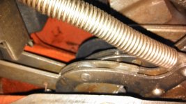
With respect to the position control cam, here is a photo of the cam installed the correct way.
IMAG1296 (2).jpg

This was quite an easy fix with the cover off and the cams exposed. I confirmed Big Dean's statement quoted above. In fact, with the quadrants removed, you have to rotate the rod that controls the position cam outside of its normal range to get it back in place. This was very easy and it actually happened a second time after I replaced the roller but I knew what had happened and in less than a minute, had it corrected. You just have to see and feel it in the right place.

Anyway, finally got the lift cover adjusted using the I & T manual and reinstalled. Then did the final adjustments through the draft response panel. The oil tube that comes up from the pump to the lift cover was rather difficult to get installed but I believe that was due to the tight machining in the pump. Hooked up a 7' light duty blade today and dragged the driveway. Seemed to work great, hadn't used the blade before as the bushhog was hooked up when I bought it but it lifted all the way up. At least until my neighbor came by and stood on the rear of the blade. It would not lift the blade with his additional weight (approximately 200 pounds). He got off and it would lift it fine. I'm guessing it won't do well with the bushhog or a recently acquired Ford 201 flex-o-hitch disk.

I am open to any suggestions as to how to get the three point hitch to lift more weight. I contacted the dealer about adjusting the lift cover and making the final adjustments and was told it would be time and material at $85/hour. He also said it could take 2 - 6 hours. Any thoughts on this?

Thanks, Michael
 
   / MF 135 Hydraulic 3 Point Hitch Questions
  • Thread Starter
#22  
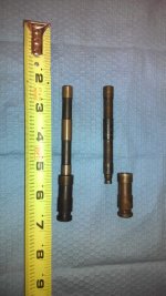
Forgot to post a picture of the new vs. old hydraulic linkage pivot shaft. It actually is a two piece pin but there is a sort of brass snap ring that holds them together. The old one had a lot of slop in it.

IMAG1287.jpg
 
   / MF 135 Hydraulic 3 Point Hitch Questions #23  
G'day termyte14.
To complete the internal and external hydraulic adjustments requires that before beginning to adjust it is important that the Draft Spring is adjusted and functioning properly, read the it manual ,this will give you the necessary information.

To check the hydraulics , fit a heavy implement to the tractor then bypass the toplink that is install a chain or a load rated sling in place of the toplink and instead of connecting where it would normally fit ,connect it to the long pin just below,by doing this you are temporarily removing the draft control spring from the system, Repeat be very carefull ,if the tractor lifts the implement you will have to remove the draft assembly and adjust as per manual, most often this will require replacement of the parts inside ,you will know what i mean by the time you have finished.
happy Days.
Hutch.
 
   / MF 135 Hydraulic 3 Point Hitch Questions
  • Thread Starter
#24  
Thanks for the input Hutch. I had completely pulled down the draft control spring and adjusted per the manual. I will try hooking up an implement and connecting to the pin you refer to. I have a few questions though. You say to be very careful, what specifically do I need to be cautious about? If the tractor lifts the implement in this scenario, are you saying I will need to probably replace the parts within the draft control spring assembly or parts on the underneath of the cover? Hopefully I will have a chance to look into this issue this weekend.

Thanks again for the input.

Michael
 
   / MF 135 Hydraulic 3 Point Hitch Questions #25  
G'day termyte.
As always I ask that when doing your own repairs that you be mindfull of all danger including that which may happen as a result of in this case the Temporary Chain or Sling breaking under load, keep children and adults well away from the posssible danger.

The draft spring adjustment:
Step one is to install a Hydraulic Pressure gauge , this will help you diagnose and locate the hydraulic problem .
The gauge can be fitted either into the front left hand side of the lift cover, remove the three eighth" npt allen headed grub screw and fit the gauge.
The gauge should be good for Three thousand PSI to be safe.

The draft spring if incorrectly adjusted will have an influence on the operation or otherwise of the Three point linkage ,to test with an implement attached ,one that will put a bit of weight on the toplink .

Remove the sideplate to give you access to the hydraulic control lever.

Set the Draft Lever in the UP position and for the moment leave it there.

Set The engine speed at about 900 to 1000 rpm then using the Position control lever slowly raise the implement and at the same time watch the draft spring and note the amount it "Stretches", pulls out,if adjusted correctly it should pull out about half an inch at most ,and lift the linkage all the way into the TRANSPORT Position if not, still with the Position control lever in the Transport position Look inside then Slowly move the position control lever Up and down watching what the control valve is doing, if you see the control valve moving Forward ,into the Neutral position BEFORE IT ACTUALLY REACHES THE TRANSPORT POSITION on the linkage ,Carefully with your fingers push the lever gently to the rear Forcing the control valve if you like ,if this gives you a favourable result you may if lucky ,be able to adjust the fine tune Knurled nut on the control lever if not let me know what results you get.
Happy Days.
Hutch.
 
   / MF 135 Hydraulic 3 Point Hitch Questions
  • Thread Starter
#26  
OK, I definitely understand the cautionary note. I'm going to have to try to find a gauge though. I'm hoping a local farmer may have one I can borrow.

Once I find a gauge, do I connect the implement as I would normally, or do I still bypass the top link?

I am familiar with the control lever and knurled nut you are referring to so I just have to find a gauge now.

Thanks again, Michael
 
   / MF 135 Hydraulic 3 Point Hitch Questions #27  
G'Day termyte .
Yes ,try the hydraulics with the linkage hooked up as you would normally ,then do the same again with the temporary chain/sling and compare the results .
Regards.
Hutch.
 
   / MF 135 Hydraulic 3 Point Hitch Questions
  • Thread Starter
#28  
Ok, I got a 3000 psi gauge from Northern Tool. Got it installed today and did some testing. I have not drained any oil or removed the side inspection plate but here are my results.

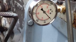
I first checked the gauge without an implement attached to the three point hitch. The draft control lever is in the full up position and the position control is moved through the full range stopping at the transport position. The gauge reads 0 psi through the full range of motion. When the position lever is placed into the constant pumping position, you hear the relief valve begin to sound and the gauge jumped to about 2800 psi. I didn't get a picture because I didn't want to leave the system in this situation that long. Here's a picture of the set up.

20140321_172238.jpg20140321_172249.jpg

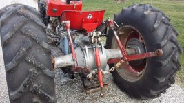
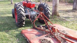
Next I connected a bush hog as you normally would through the top link. The levers were operated in the same manner and the front of the bush hog wouldn't even come off the ground. The gauge barely came off 0 psi. Here's a couple pics:

20140321_170232.jpg20140321_170247.jpg

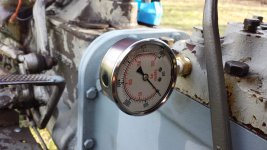
Last I removed the top link connection and attached a chain from the top link connection of the bush hog to a bolt below the top link connection on the tractor. I operated the levers in the same manner and it raised the bush hog through the full range of motion. The gauge read about 700 psi with the draft control lever in the full up position and the position control lever in the transport position. Here are some pics:

20140321_171342.jpg20140321_171359.jpg

Based on the above information, what is my next move? Any guidance would be greatly appreciated.

Thanks, Michael
 
   / MF 135 Hydraulic 3 Point Hitch Questions #29  
G'Day termyte.
Excellent photographs.
So now we know the pump is o.k although the pressure is a bit high , should be around 2500 <>psi.

Remove the sideplate as suggested and with the toplink in the Normal operating position that is attached to the draft link , and again the draft lever all the way up, slowly raise /move the Position control lever towards and stop at the transport position watching what the control valve is doing ,if you find that the control lever is returning the control valve to neutral before the linkage reaches the transport position gently assist the control linkage and move the control valve to allow the pump to raise the implement, if this has the desired effect you will have to remove the draft link assembly ,the one with the big spring inside, remove complete and readjust when you are happy all is good with this part ,thoroughly clean out the housing and make sure the sensing rod inside is properly located ,that is it should be sticking out about 1/4 inch if all good reassemble and test ,you may have to adjust the compression on the spring to fine tune the controls, this is done by Tightening the big NUT behind the dust boot ,adjust say 1/4 turn at a time and test till you get a satifactory result.
Let me know the results and we can go from there.

Happy Days.
Hutch.
 
   / MF 135 Hydraulic 3 Point Hitch Questions #30  
What happened when you placed the lever in constant pumping with bush hog on the upper 3 point position (draft control)?

I agree that your pump is fine, you just have maladjusted linkage.

Aaron Z
 
 
Top