stuckmotor
Super Member
- Joined
- Sep 23, 2009
- Messages
- 7,641
- Location
- Lower Up State S.C.
- Tractor
- AC WD 34 hp/3500 lbs MF 261 60 hp/5380 lbs
Thanks Shield Arc. I guess I was wrong.
You are welcome!Thanks Shield Arc. I guess I was wrong.
Well I'm no pro, but that's how I've been doing it for years.

Shield Arc,
Would you do it with an AC welder? That's all I have.
lol, I think our terminology is getting confused, caps don't fill holes ( as in a zero volt reference and up ) they smooth out " ripples"/"noise" of a specific voltage and are also used as storage cells. .

lol, I think our terminology is getting confused, caps don't fill holes ( as in a zero volt reference and up ) they smooth out " ripples"/"noise" of a specific voltage and are also used as storage cells. .
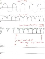
View attachment 456660
here, this might help. and for the other EE's out there, this drawing is OBVIOUSLY not scaled.. freq, etc, waveform errors, etc. it's just a pictogram.
Skyhook... the first line shows half wave dc, an ac wave form ran thru a diode and it chops one half off as the diode oposes current flow in one direction.
the next line shows full wave dc, either a transformer and 2 diodes, or 4 diodes aranges so that the lower waveform is tossed 'up top'.. this makes for a riple-dc.
Now, if you take a capacitor and put across the ground reference and the positive test point. the capacitor will 'fill in' the space between those waveforms. ( of course you must have a large enough cap to filter with... loaded or unloaded circuit will effect that, yada yada..
the third line shows the full wave dc with a steady state line over it and a green hash shaded area.. that's what the cap is doing, the green shaded area.
to your vom, the 4 line is what gets reported... steady state dc.
I considered doing this drawing, but I was lazy. I am glad you posted it.