Control valve confusion

/ Control valve confusion #1  

Elder Massey

New member
Joined
Mar 23, 2014
Messages
9
Location
Peru Indiana
Tractor
1957 MH 50
Hi, I am a new member who registered after reading numerous posts. I have zero experience with hydraulics. Here's what I am attempting to do.
I have a 1957 Massey Harris 50 purchased about a year ago with a Freeman front loader w/ trip bucket. It has the two spool "between the legs" controls. Left-3 pt. Right- auxiliary which goes via 2 hoses to rear quick connects. From the rear a hose connects to single action lift cylinders on the front loader. Everything works fine though a little slow.
I have purchased a single spool Chief P80 (cv1) (3 way or 4 way) to add tilt control for 2 double acting cylinders I am adding to the bucket. (Building my own) The control instructions have me confused about which port to use for the tank return line. See attached "instruction" sheet. ?????
Having read some I assume that (1) I need a closed center while in neutral. This control has 5 ports. P for pressure? 2 work ports. T for tank which is plugged. Then a "N" port. Either T or N needs to be plugged. Stock, the T port is plugged.
Question 1- do I use port T or port N for the tank return? I can not make sense of the schematic/ instruction sheet.
Question 2- I have read where there is a plug on the left side of the Massey hyd cover plate which can be used for a hydraulic return line. I have purchased two manuals and neither say anything about this or the 2 spool control ( apparently an add on though original).
Any information and help would be greatly appreciated. I have been a journeyman electrician for 3 decades so thinking in terms of "flow" is certainly not new to me, but this has me pulling my hair out...that is.. what little I still have.
 

Attachments

  • hyd control.jpg
    hyd control.jpg
    339.2 KB · Views: 1,438
/ Control valve confusion #2  
I don't believe you will be able to add a single spool valve to your system to add bucket tip. I have a Massey 135 with a two spool valve on top the transmission, in front of the seat the same as you. To add another valve downstream from your Massey two spool valve will require power beyond. I have never seen a port or a fitting available to allow this. You cannot tap into the top cover hydraulic ports for a pressue line to the new valve and then run a return line to the plug in the top cover or the fill plug as you mentioned. This creates an open center system and would not allow you to operate the three point or the lift for the loader. This is the reason that power beyond is required. The only way I know how to accomplish this is to purchase a new two spool valve and run the pressure line and return line to the rear remotes. Then the loader and tilt cylinders would connect to the new valve. You will have to have the Massey left hand valve centered and the right hand lever pulled and held toward the seat to get flow to the new valve. I assume that this tractor has constant pumping on the position lever same as a 135.

I have added a complete auxiliary hydraulic system to my 135 including pump, tank and single valve, I use for the loader lift. I currently use the remote on the tractor to operate the bucket tilt. Now that I have proved out the design and operation, I have purchased a two spool joystick valve to add to the system so I can operate the loader entirely off the auxiliary system. I have done this for two reasons, one, the 135 has only one valve for auxiliary use and the 135 hydraulic system only delivers 4.5 gallons per minute so the loader runs pretty slow.

This is my experience and believe it will be the same for the MH50. Hopefully someone will post if this is incorrect.

namyessam
 
/ Control valve confusion
  • Thread Starter
#3  
Thanks for your response. Obviously you are correct. Now I understand why the previous owner connected the FEL lift to a rear quick connect...so he could disconnect it if he attached something else. Why he ran two pressure hoses to the rear remains a mystery. I was assuming that I had constant pumping to the second hose. You know what they say about making ***-sumptions.
I was aware of the low GPM out. My 3 point works very well for my purposes and while slow the loader has plenty of power. However, a separate system makes sense and will surely be faster and more powerful.
What did you install, a belt driven or a PTO pump?
 
/ Control valve confusion
  • Thread Starter
#4  
I am also curious if I could make this work with a diverter between the lift and tilt functions?
 
/ Control valve confusion #5  
View attachment 366808
Thanks for your response. Obviously you are correct. Now I understand why the previous owner connected the FEL lift to a rear quick connect...so he could disconnect it if he attached something else. Why he ran two pressure hoses to the rear remains a mystery. I was assuming that I had constant pumping to the second hose. You know what they say about making ***-sumptions.
I was aware of the low GPM out. My 3 point works very well for my purposes and while slow the loader has plenty of power. However, a separate system makes sense and will surely be faster and more powerful.
What did you install, a belt driven or a PTO pump?

Are you saying that the previous owner ran two hoses from the right hand side of the valve to the rear, one from the front fitting and one from the rear fitting. If this is what you are saying, it is to be able to run a double acting cylinder. There are what they call switch valves either in the front of the valve or on the back of the valve just under the spool (mine are in front) they have a standard screwdriver slot in them and they control the valve function for single acting (which you have) or double acting. Both the left and the right hand one should be screwed out. If you screw them out gently till they stop it will operate a single acting cylinder. Screw them in gently till they stop for double acting. For the single acting operation, when you lower your loader oil must flow from the lift cylinders back to tank, also the oil coming from the pump must have somewhere to go rather than deadheading to the quick disconnect you are not using on the back of the tractor, so the switch valve directs this oil back to tank also rather than blowing the relief valve.
I've been thinking the dirvirter valve question and can't think of any way that would work.

I built a frame on the front of the tractor to mount a pump driven off the front crankshaft pulley.View attachment 366802

there an image of my auxiliary valve at the top 255jpg. Don't know how it got there LOL
 
Last edited:
/ Control valve confusion
  • Thread Starter
#6  
My setup appears to be very different. Both hoses going to the rear are pressure. I had assumed that I could feed pressure to the new control and have a separate return for the double acting cylinders. Clearly it was not going to work.
DSCF0393.jpgDSCF0394.jpg

If I am thinking correctly (probably not) I could block the existing control flow to the hose feeding the single cylinders and divert the pump flow to the new control for tilt and curl.

I also wonder if by switching flow between the two hoses I could use the new cylinders as single acting and eliminate the new control valve.

I use the FEL more than anything else and the trip loader is a real pain when it is -20 out and you are trying to move snow. I'm too old for it. Thanks again for your help.
 
/ Control valve confusion #7  
My setup appears to be very different. Both hoses going to the rear are pressure. I had assumed that I could feed pressure to the new control and have a separate return for the double acting cylinders. Clearly it was not going to work.
View attachment 366819View attachment 366820

If I am thinking correctly (probably not) I could block the existing control flow to the hose feeding the single cylinders and divert the pump flow to the new control for tilt and curl.

I also wonder if by switching flow between the two hoses I could use the new cylinders as single acting and eliminate the new control valve.

I use the FEL more than anything else and the trip loader is a real pain when it is -20 out and you are trying to move snow. I'm too old for it. Thanks again for your help.

You should only have pressure on one hose at a time, when you pull the lever back pressure is on one line, when you push the lever forward pressure is on the other line. Sounds like the switch valve is in the wrong position. In the picture of my valve the switch valve is just under the handle. covered with oil and dirt. Turn it out and you should have pressure only on one line. You may need to change the line going to the loader to the other quick disconnect. The switch valve only controls the flow when the lever is pushed forward.
I have attached a picture of the back of my tractor. I am using both quick disconnects for one double acting cylinder on my bucket. The quick disconnects look the same.
 
/ Control valve confusion #8  
I may have found something that may help. I went to:

agcopartsbooks.com
guest user
view books
Top left hand corner hover over browse
click on browse books
click on Massey Ferguson
click on parts books
click on tractors
click on agricultral wheeled
scroll down to 50 tractor (Harris and Massey)
scroll down to Auxiliary hydraulic valve.

I believe this is the valve you have on your tractor. The big advantage is that it is expandable, if you can find the part. Under the auxliary valve is a listing for a auxiliary hydraulic valve (3rd spool attachment) If you can find this add on valve, this would allow you to hook the bucket control to your existing valve without any other modification except for hoses to your bucket cylinders. This would be a neat and clean setup. Start with taking pictures of your present valve and send it to tractor salvage yards with your tractor make, model, and year. Good luck and Keep us posted.

namyessam

BTW I don't see switch valves on your valve as I have on mine.
 
/ Control valve confusion
  • Thread Starter
#9  
Well, If I can find one that would sure simplify everything. But, it begs the questions-
(1) if my unit is expandable as it appears to be then where does the third spool pick up pressure and allow return.
(2) why couldn't these ports be tapped into to use another remote.

I've been outside taking a close look at my control which poses the same questions. I do not have switch valves or any external adjustment screws. What I have are 4 ports- 2 of which feed the rear hoses and the other 2 are plugged. I need to determine exactly what their functions are relative to the three positions of the control. It seems to me that they are 2 pairs in parallel.
You were correct that I do not have pressure on both rear hose at the same time. While I have used both, I did not pay attention to what way I was moving the control arm. Again, it seems that one pair reversible in parallel would operate double action cylinders leaving the other pair for single action lift cylinders. But this is pure speculation and I have hunted for an operational diagram and spec sheet for a long time. They seem non existent.
I have seen isolator valves for these old Massey's for sale on other websites. Again I need more information than they provide. There are also aftermarket 3 spool controls . It all seems like a lot of time and money to be able to tilt and dump a front loader bucket.
Tomorrow I am going to buy some hoses and test everything. I know that my pressure release valve works so hopefully I wont damage anything or myself. LOL Thanks again for your help.
 
/ Control valve confusion #10  
Well, If I can find one that would sure simplify everything. But, it begs the questions-
(1) if my unit is expandable as it appears to be then where does the third spool pick up pressure and allow return.
(2) why couldn't these ports be tapped into to use another remote.

I've been outside taking a close look at my control which poses the same questions. I do not have switch valves or any external adjustment screws. What I have are 4 ports- 2 of which feed the rear hoses and the other 2 are plugged. I need to determine exactly what their functions are relative to the three positions of the control. It seems to me that they are 2 pairs in parallel.
You were correct that I do not have pressure on both rear hose at the same time. While I have used both, I did not pay attention to what way I was moving the control arm. Again, it seems that one pair reversible in parallel would operate double action cylinders leaving the other pair for single action lift cylinders. But this is pure speculation and I have hunted for an operational diagram and spec sheet for a long time. They seem non existent.
I have seen isolator valves for these old Massey's for sale on other websites. Again I need more information than they provide. There are also aftermarket 3 spool controls . It all seems like a lot of time and money to be able to tilt and dump a front loader bucket.
Tomorrow I am going to buy some hoses and test everything. I know that my pressure release valve works so hopefully I wont damage anything or myself. LOL Thanks again for your help.

I agree that you do not have any switch valves, I discovered that on agcopartsbooks.com.

The two ports on the left hand side are plugged because that is the valve that operates the three point hitch. All oil flow is done internally, Oil from the pump comes up a tube called the standpipe into the lift cover. From there it enters the auxiliary valve, with the left lever pulled toward the seat and the right lever centered the oil flows to the control valve which controls the three point hitch. using the position lever on the right hand side of the seat, the three point can be raised or lowered or held at any position automaticly.

With the left hand lever centered, the position lever in the constant pumping position, oil is then directed from the pump to the auxiliary valve and when the right hand lever is pulled or pushed it directs oil to one of the quick disconnects. When using a double acting cylinder oil is forced on one side of the piston and the oil from the other side returns to tank via the opposite quickdisconnect and auxiliary valve. When the hand lever is moved the other direction the flow is opposite. I think you said you were a journeyman electrician in the start of the thread, The hydraulic valve is almost the same as a single pole double throw switch. the pressure line (oil from the pump) is the power wire and each quick disconnect is the load. The only difference is when power is applied to one hose the other hose becomes the neutral wire. sorta?? I am by no means trying to insult you but I get the feeling you are confused. You could purchase a 3000 psi hydraulic gage and also purchase a Pioneer male tip and install the pressure gage to it. It then can be inserted into your quick disconnects so you can see when you have pressure or no pressure relative to the valve positions, forward or back.

as for the expandable valve, good question, the right hand side has a cover plate and there must be some ports available under it to allow both pressurized oil and return flow. I suppose someone with a machine shop could build a different side plate with tapped holes so you could connect the valve you bought to it. I never thought about that.

namyessam
 
Last edited:
/ Control valve confusion #11  
One other bit of info. With your single acting lift cylinders on the loader, the weight of the loader arms, bucket and anything in it is the only thing returning oil to the tank. There is no pressure from the pump to the cylinders although there is pressure on the opposite unused quick disconnect. It would be better if you could run it to tank rather than blowing the relief valve every time you lower the loader.

namyessam
 
/ Control valve confusion
  • Thread Starter
#12  
No, I'm not confused about the operation of my controls or flow and return or how my levers work. I use the position and draft controls on the 3 pt. all the time. The position control interacts with the auxiliary spool and must be in the up position for aux pumping and of course are supplied by the standpipe. I have been inside the gear case and know what is in there to check and service/clean the pump. I can not say the same about the auxiliary controls.

There are many possible spool configurations which obviously provide for return. This thread began with questions about spool and port configurations.

I have 4 ports on the auxiliary side and nothing is plugged on the 3 pt. side of the control which is why I speculated about there being two pairs of parallel ports. But I will find out tomorrow. While an inline pressure gauge might be a good investment, it is not necessary.

The isolator/diverter is a viable possibility and for a hundred bucks may also be the cheapest and easiest way. Massey Harris MH50 Hydraulic Diverter Valve (S.60032) Thanks for your opinions.
 
/ Control valve confusion #13  
Hi, I am a new member who registered after reading numerous posts. I have zero experience with hydraulics.
Any information and help would be greatly appreciated.

I must have misunderstood your first post. I'm sorry I wasted all this time trying to help. I did gain some valuable information that I will remember for future use though. I hope everything works out for you. This is the last you'll hear from me.

six two and even, over and out.

namyessam
 
Last edited:
/ Control valve confusion
  • Thread Starter
#14  
Good. I don't want to hear from you and there are a number of very good reasons why. That is why I am posting again, and for others that may have an interest in the problems, and real solutions presented instead of egotistical nonsense. Put simply and directly, your conclusions are not only baseless, they are absurd and flat out insulting. Worse, they are the kind of ex-spurt advice that can cause a serious injury to person and/or property. Unfortunately far too many have not learned to be wary of self styled "internet experts." Power transmission whether electrical, hydraulic, or other is very dangerous if you don't know exactly what you are dealing with. In the case of my equipment it is very clear that you don't and it involves far more than what you "believe." I stated over and over that I simply didn't have the proper information.

I stated that I am a lifelong electrician/ skilled tradesman with zero hydraulic experience. That was relative to the question posed i.e. "control valve confusion" yet it would seem that anyone with common sense would know the relationship between the two. It is a fact that while I am now retired, I spent close to 40 years wiring industrial machinery, factories, and large scale commercial and industrial projects. The last couple of decades were spent in supervisory capacities yet I never gave up hands on work. My point is that I learned, and passed on, how to be safe. That means knowing both the proper procedures and a mandatory knowledge of the equipment being connected...other wise you don't do it. Generally, If it didn't have an engineers stamp on it, I wouldn't touch it. But even then, I checked for myself and made sure everyone around me did the same. Even retired I still get calls from engineers asking how something should be done.

So I am not going to parse words over whether I have experience. With the issues at hand I don't. But I have realistically connected in excess of ten thousand electro-mechanical control systems. It is absurd to conclude that I would not know the difference between a single action and double action cylinder or how a pressure relief valve works e.g. need for tank return among many other things. If I didn't, I sure as **** wouldn't attempt to do what I am doing.

So did I say that I "blow a relief valve" every time I lower my loader bucket? No. If I ever did, which I haven't, the key would go to off and would not be turned back on until I found out exactly what caused it and corrected it. Anything else would be absurdly stupid. What I said was is that I had pressure at both rear quick connects and had to find out exactly what port functions were involved. I didn't say that I was "deadheading" and blowing the relief valve. That was one of your (baseless )conclusions and totally removed from the question presented. Now that I have tested it, I have the answer. But I am going to back up to the original question posted because the answers, and the methods lie there.

One more time:
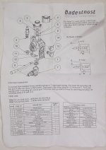
I bought a Chief directional control to use as a 4 way closed center to control 2 double action cylinders. I posted the "instruction" sheet with the schematic. It is interesting to note that I found others who had the same "confusion" and no one ever answered the questions posed.

Look at the schematic for the 4 way operation. In the center neutral position it is closed. Flow (P) bypasses and returns to the tank.(T) In the other positions work ports A and B are also diagrammed and again return is routed to T as tank. That is the correct operation for my purposes.

Now look at the directional control valve body and you have ports P- A- B- T-and N. Nowhere is on the schematic is it shown that the Tank return port is plugged and nowhere is port "N" depicted. Thus, I posted my "confusion" hoping to find someone familiar with this Bulgarian spool and the handful of plugs they provide. I provided the function sought . No luck getting an answer. So I simply used the plugs and drew my own schematic by using compressed air to trace the control spool functions relative to the ports while operating the control lever. Not exactly rocket science but a pain. Port N can be used for tandem operation or your so called "power beyond." "P' enters and is bypassed to the pressure control valve and continues internally to T. For my purposes all I had to do was remove the plug from T and plug N. It now functions exactly as the schematic shows. It is impressive how this control can be used but the "instructions" are incomplete and wholly worthless. A schematic is one thing. Knowing the flow paths through the valve body or manifold is another. I don't connect anything until I know and the only way to tell if it will function if that info is not provided. If they are going to sell these, they should diagram everything. I looked at some Prince products and they provide it.

I used the same air method on the tractor auxiliary double spool. Of course I had to remove it. But it needs cleaned, checked, and painted. As I stated, I had a very different piece of equipment. For those that have this aux control spool and want to add another spool with it, you can...just like I thought in the beginning although not where I thought I could tap into pump flow. Yet there is a external port for pump pressure. So as a courtesy I will provide the info.

I have no idea whether this can be done with other old Massey models. I have a Massey Harris 50 made in 1957. I am the second owner. The hour meter stopped at 45,000+hours. The loader was made by Freeman here in Peru Indiana and was purchased with the tractor. It started every time this winter even in 40 below wind chill weather. While its not pretty, this old work horse just keeps going just like I plan to. The loader bucket is shot and I am fabricating a new one. Overall, the tractor has been very well maintained.

All internal valve body passages were traced from the standpipe using compressed air:

1. The left or three point spool is single acting.
2. The right is double acting. I stated that I had pressure at both rear hoses and had used both. This spool has likely been used with single acting lift cylinders for more than 50 years and has never blown a relief valve that I know of. Tracing the internals reveals how this operates and is perfectly fine for either single or double action cylinders. See pics and other info below.
3. I began by removing the side cover and as I thought, I found pump and return ports.
View attachment 367094

The center and 2 inside ports go directly to the pump. However, the center is affected by the spool but interestingly also supplies pressure to the pump cover.
View attachment 367096

4. While I had stated that I had pressure from the rear hose quick connect, I didn't but was close. On the rear of the control there is a port chamber controlled by spring loaded valve which can be adjusted to prevent or allow double action flow.
View attachment 367097

5. This pissing match came about from my belief that I could add a spool and pick up straight pump flow when I did not pose that question. Here it is. Return can be routed to the lift cover or the aux spools. This leads me right back to the original intent and question. Use a closed center 4 way 3 position directional and it will work.
View attachment 367098

While I will most likely fabricate a side cover rather than use this old one , I haven't decided. The side cover I thick and old seasoned cast iron so there is t also the possibility of drilling and tapping into the side for easier access and compatible fittings. I bench tested this and know it works.

Other questions PM me. You wont see me back on this forum. For Namyessam, shove it.
 
/ Control valve confusion #15  
When I was employed at a JD dealership I always dreaded if a MF with hyd problems came in the shop. IMHO MF made their hyd system too complicated but it might be I just wasn't familiar with their hyd system.
 

Marketplace Items

Iranch IRGC40 (A60463)
Giyi XKH39 (A60463)
Giyi XKH39 (A60463)
500BBL WHEELED FRAC TANK (A58214)
500BBL WHEELED...
Dodge Charger (A56859)
CAT 289D3 (A58214)
CAT 289D3 (A58214)
(250) Iranch Safety Traffic Cones (A60463)
(250) Iranch...
 
Top