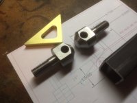
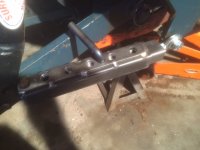
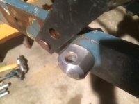
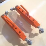
So, corresponding again with Mark H. highlighted a concern I have over the design of the tractor-end of npalen's stabilizers. As you can see from the area circled in red:
...his design relies on a spherical male rod end (hereafter "SMRE") that, as shown (bolted to the outboard side of the vertical mounting ear), doesn't appear to permit much in the way of right to left movement.
Thinking about this helps to explain why the tractor-end of npalin's male square stock features the bevel - he needed to produce a little more effective range in the SMRE's in order to produce the range of motion he needed. In other words maybe, in practice, the SMRE's he selected - in conjunction with the beveled-end of the solid square stock - permit the full range of left to right movement that he needed for his particular collection of implements. However, unless he responds to my various requests for input, we'll never know if this is true (or if, in practice, this was a fatal flaw of his design). [Note - npalen's last contribution to this forum is dated 31 January, 2025, and a little digging revealed that his health has not been good and so he may never chime in - I wish him well.]
However, in the interest of perhaps improving upon his design, I'm exploring a couple of variations that address this limited left to right travel issue.
I'm no expert here, but after a little research I found that there exists a variation of SMRE's known as "high misalignment"-type or "necked".
Here's an graphic which compares a "standard" SMRE against a High Misalignment SMRE (the "necked" SMRE is third down):
As you can see, as the range of motion increases, the ID of the bearing (and, correspondingly, the wire size of the intended fastener) decreases.
Here's what a "necked" SMRE looks like:
Refer
here for a discussion of the various type of SMRE's and
here for more, specifically, on high misalignment SMRE's.
There are also what are known as Heim joints which, from what I can ascertain, are simply more robust versions of SMRE's (more robust but often or always more limited in terms of their range of motion).
Here's a discussion on the advantage and disadvantages of each.
There's also the option of using a standard SMRE along with a Ball Joint Rod End Reducer to effectively increase the range of motion of a given SMRE.
Here's what they look like.
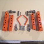
And here's a photo depicting one alternative approach to npalen's one-sided use of a standard SMRE (this appears to be a standard SMRE matched with two ball joint end rod reducers mounted in a one-sided fashion):
As you can see, this setup permits a very wide range of motion.
However, given that whatever version of SMRE is chosen must bolt to the vertical mounting fin (in order to align with what Mark H. explained to me is the "common shaft"), the fin itself becomes the limiting factor. One can only move the stabilizer so far left or right (depending upon whether we're talking about the left or right stabilizer) before it makes contact with the vertical mounting fin, even if one takes steps to space the SMRE away from same.
One way to avoid this issue altogether is to do away with the SMRE altogether and instead make use of a shop-built interface like the one I inadvertently depicted earlier (shown again below and identified by the red arrow):
One caveat: since, in npalen's design, adjustment of his stabilizer is characterized by the emergence of the male solid square stock from the tractor-end of the stabilizer (the version shown above being kind of a mirror image), the shop-built fitting shown above (identified by the arrow) would need to be installed on the tractor-end of the solid square stock (
not on the end of the female square tube stock as shown above). This might negatively impact the overall adjustability of the stabilizer given that, in contrast to npalin's use of a male SMRE, the female square tube stock will not be able to slide entirely over the tractor-end of the male solid square stock - its range of travel will be limited by the bulkier shop built fitting. This means that the square tube stock may end up a little shorter than in npalin's version - further limiting the range of adjustability already inherent with such a short telescopic stabilizer.
However, the various advantages of the shop-built fitting are that it not only maintains the crucial "common shaft" positioning, but it also moves the left and right pivot point out beyond the vertical mounting ear. Like npalen's SRME, it would mount to one side of the vertical ear (likely, but I guess not necessarily, on the outboard side) so that would be consistent. But the issue of limited left and right travel would be solved.
I envision that the shop built fitting would be installed onto a bolt that would make use of four washers and three nuts; one nut clamping the bolt firmly in the vertical mounting ear and one serving as a jam nut, to ensure that the tube portion of the fitting (which provides the up and down range of motion) could remain a little loose to permit the fitting to pivot up and down.
The other advantage of the shop-built fitting is that it precludes having to first source and then trial and error various types of SMRE's, a huge factor for those of us who live in rural areas and don't have ready access to niche components like these.
Finally, the shop-built fitting also produces another tool-less disassembly point in the stabilizer assembly given that it introduces another pin and split pin fastening point. I'm all for maximizing the number of places whereby a user can disassemble a series of linkages like these without needing tools. Plus, the movement inherent in a "lose" joint like this will only further contribute to assisting with the lack of adjustment slots in the stabilizers.
