3ph Stabilizer Build - Show and Tell Pics

   / 3ph Stabilizer Build - Show and Tell Pics #1  

npalen

Elite Member
Joined
Nov 17, 2009
Messages
3,478
Location
Beloit, KS
Tractor
Kubota B9200 HSTD and Mahindra 3015
The telescopic type stabilizers are not available for my Kubota B9200 as the space envelope is very limited for conventional lengths. The stock stabilizers are turn buckle type and hard to get at for adjusting because of the tight space next to the tires.

I visited with Mark Hodge (stabilworks) and he doesn't offer this unconventional size so I decided to fab in the shop using 1 1/2" square tubing for the female and 1 1/4" square shaft for the male.

Had to machine a little off the thickness of the shaft to give it sliding clearance inside the tube. The tube needed some wall thickness so welded 1/4" x 1" flat to the top and bottom before drilling the holes.

Made the two eyebolts out of 1 1/2" round and single pointed the threads as I have no 5/8"-11 die. They are overkill sizewise but will work okay.

The second and third pictures above were taken with the right rear tire removed. The lift arms are a tight fit inside the tires when pivoted outwards.

Thanks for all who responded with suggestions to the thread below. I decided to go without slots for the time being and see how that works. There is enough slop in the 30 year old tractor to allow some lower arm lateral movement even when pinned.

http://www.tractorbynet.com/forums/customization/374400-need-help-hole-spacing-3-a.html
 

Attachments

  • STABILIZER-25.JPG
    STABILIZER-25.JPG
    83.8 KB · Views: 270
  • STABILIZER-21.JPG
    STABILIZER-21.JPG
    89.6 KB · Views: 350
  • STABILIZER-22.JPG
    STABILIZER-22.JPG
    82.5 KB · Views: 275
  • STABILIZER-23.JPG
    STABILIZER-23.JPG
    83.6 KB · Views: 395
  • STABILIZER-24.JPG
    STABILIZER-24.JPG
    78.7 KB · Views: 438
Last edited:
   / 3ph Stabilizer Build - Show and Tell Pics #2  
Very nice. My only suggestion would be to chain the pins so they can't get lost. If you were buying those links, they'd be $200, for sure.
 
   / 3ph Stabilizer Build - Show and Tell Pics #3  
Those look great!
 
   / 3ph Stabilizer Build - Show and Tell Pics
  • Thread Starter
#4  
Very nice. My only suggestion would be to chain the pins so they can't get lost. If you were buying those links, they'd be $200, for sure.

Good idea. I added 1/16" cable lanyards.
 
   / 3ph Stabilizer Build - Show and Tell Pics #5  
Since this thread isn't linked to from the other related thread I just now made that connection. Also, the google search algorithm doesn't point to this thread so let's try to change that. Kubota B9200 HST 4WD telescoping stabilizers.

OK, so, it is possible to utilize telescoping stabilizers with the B9200 and to do so apparently without having to add wheel spacers to the rear wheels (to increase the distance between the rear tires).

npalen, if you aren't offering to fabricate these for sale to other people (DM me if you are), are you at least willing to provide some additional user experience and dimensional data to assist those of us who want to fabricate our own? I can glean some from the photos you uploaded but some additional info would be helpful.

Specifically:
  • Do these actually work in practice? And, if you could do it again, would you and would you make any changes?
  • Can you please verify that you accomplished this installation without needing to install wheel spacers?
  • Can you upload (or otherwise provide) the engineering drawing that you prepared (visible in one of your photos) that details the dimensions of the custom eyebolt? I don't own a lathe so that aspect of the build will need to be accomplished by a third party and likely someone who won't have access to my tractor,
  • Why did you elect to fabricate the custom eyebolts rather than somehow making use of the OEM eyebolts? The latter permits up and down movement and a twisting movement while, in contrast, you're custom eyebolt only swivels left and right. Do you find this limiting in practice?
  • What is the degree of the bevel on the angled end of the solid square stock stock (the "tractor-end" of the flat stock) that you've tapped and threaded to accept the spherical male rod end?
  • What's the spec on the spherical male rod ends you used and, just to make things really easy, of the other fasteners you ended up using?
  • How long is the "male" solid square stock? (measured to the long end of the bevel and, if it makes sense, the short end as well)
  • How long is the "female" square tube stock? I note that you relieved material at one end from the sides of the tube stock to permit the custom eye bolt to swivel - some detail on this feature would be most appreciated.
  • How long are the pieces of the 1/4" x 1" flat stock that you used to reinforce the top and bottom of the tube stock and which also reinforce the mounting location for the custom eye bolt?
  • What hole drilling spacing pattern for the adjustments holes did you end up using?
  • What's the pre-bent length and diameter of the adjustment pin? I note that someone suggested adding a chain and that you subsequently ended up installing 1/16" cable lanyard to prevent loss (I assume this explains the tiny holes drilled both into the ends of the stabilizers and into the angled adjustment pins).
  • Did you end up having to do any post-installation modifications (like adding a slot for float) that aren't reflected in the images you originally uploaded? Did you find a slot is needed? The only two implements I use are a Bush Hog-brand "Squealer" (I only mount and dismount this once or twice a year) and a Bush Hog-brand rear blade (installed 99% of the time and used regularly for gravel road maintenance and as a secondary snow plow plus as a attachment point for dragging logs home for milling into firewood and a tow point for periodically repositioning a log splitter) so I assume that I want to at a minimum ensure that my chosen hole drilling pattern (for adjusting the length of the stabilizers) accommodates these two implements while also leaving room for other unknown future implements. But it would be nice to know if I need to incorporate a slot or not.

    I think that about covers it. Crossing my fingers a response is forthcoming. :)
 
Last edited:
   / 3ph Stabilizer Build - Show and Tell Pics #6  
Looking at other designs of telescoping stabilizers and, specifically, for other ways of attaching the implement-end to the lower arms, here's an idea that precludes needing access to a lathe:

Simpler Connecting Method for Implement End.jpg


Either a folded end like this can be sourced/fabricated (it will need to fit around the tube stock which makes for a bulkier design) or, alternatively, working off a blend of this and the custom eyebolt idea, a bolt can simply be welded onto a cube of solid square stock (the sharp edges of the cube will need to be radiused to permit it to swivel where, like the custom eye bolt, it pivots within the end of the stabilizer). Not as elegant, certainly, but more feasible for non-machinists.
 
Last edited:
   / 3ph Stabilizer Build - Show and Tell Pics #7  
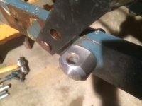
So, corresponding again with Mark H. highlighted a concern I have over the design of the tractor-end of npalen's stabilizers. As you can see from the area circled in red:

NPalen_Tractor-End_Potential Problem_Annotated.jpg


...his design relies on a spherical male rod end (hereafter "SMRE") that, as shown (bolted to the outboard side of the vertical mounting ear), doesn't appear to permit much in the way of right to left movement.

Thinking about this helps to explain why the tractor-end of npalin's male square stock features the bevel - he needed to produce a little more effective range in the SMRE's in order to produce the range of motion he needed. In other words maybe, in practice, the SMRE's he selected - in conjunction with the beveled-end of the solid square stock - permit the full range of left to right movement that he needed for his particular collection of implements. However, unless he responds to my various requests for input, we'll never know if this is true (or if, in practice, this was a fatal flaw of his design). [Note - npalen's last contribution to this forum is dated 31 January, 2025, and a little digging revealed that his health has not been good and so he may never chime in - I wish him well.]

However, in the interest of perhaps improving upon his design, I'm exploring a couple of variations that address this limited left to right travel issue.

I'm no expert here, but after a little research I found that there exists a variation of SMRE's known as "high misalignment"-type or "necked".

Here's an graphic which compares a "standard" SMRE against a High Misalignment SMRE (the "necked" SMRE is third down):

Types of SMRE.JPG


As you can see, as the range of motion increases, the ID of the bearing (and, correspondingly, the wire size of the intended fastener) decreases.

Here's what a "necked" SMRE looks like:

3064-PLUS.JPG


Refer here for a discussion of the various type of SMRE's and here for more, specifically, on high misalignment SMRE's.

There are also what are known as Heim joints which, from what I can ascertain, are simply more robust versions of SMRE's (more robust but often or always more limited in terms of their range of motion). Here's a discussion on the advantage and disadvantages of each.

There's also the option of using a standard SMRE along with a Ball Joint Rod End Reducer to effectively increase the range of motion of a given SMRE. Here's what they look like.

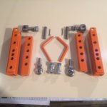
And here's a photo depicting one alternative approach to npalen's one-sided use of a standard SMRE (this appears to be a standard SMRE matched with two ball joint end rod reducers mounted in a one-sided fashion):

fk-rod-ends-keeping-it-together-in-a-misaligned-world-2020-06-04_18-28-47_380922-1440x1080.jpg


As you can see, this setup permits a very wide range of motion.

However, given that whatever version of SMRE is chosen must bolt to the vertical mounting fin (in order to align with what Mark H. explained to me is the "common shaft"), the fin itself becomes the limiting factor. One can only move the stabilizer so far left or right (depending upon whether we're talking about the left or right stabilizer) before it makes contact with the vertical mounting fin, even if one takes steps to space the SMRE away from same.

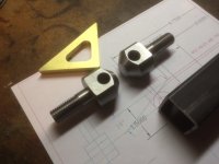
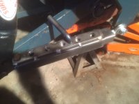
One way to avoid this issue altogether is to do away with the SMRE altogether and instead make use of a shop-built interface like the one I inadvertently depicted earlier (shown again below and identified by the red arrow):

NPalen_Tractor-End_Problem_Solution_Annotated.jpg


One caveat: since, in npalen's design, adjustment of his stabilizer is characterized by the emergence of the male solid square stock from the tractor-end of the stabilizer (the version shown above being kind of a mirror image), the shop-built fitting shown above (identified by the arrow) would need to be installed on the tractor-end of the solid square stock (not on the end of the female square tube stock as shown above). This might negatively impact the overall adjustability of the stabilizer given that, in contrast to npalin's use of a male SMRE, the female square tube stock will not be able to slide entirely over the tractor-end of the male solid square stock - its range of travel will be limited by the bulkier shop built fitting. This means that the square tube stock may end up a little shorter than in npalin's version - further limiting the range of adjustability already inherent with such a short telescopic stabilizer.

However, the various advantages of the shop-built fitting are that it not only maintains the crucial "common shaft" positioning, but it also moves the left and right pivot point out beyond the vertical mounting ear. Like npalen's SRME, it would mount to one side of the vertical ear (likely, but I guess not necessarily, on the outboard side) so that would be consistent. But the issue of limited left and right travel would be solved.

I envision that the shop built fitting would be installed onto a bolt that would make use of four washers and three nuts; one nut clamping the bolt firmly in the vertical mounting ear and one serving as a jam nut, to ensure that the tube portion of the fitting (which provides the up and down range of motion) could remain a little loose to permit the fitting to pivot up and down.

The other advantage of the shop-built fitting is that it precludes having to first source and then trial and error various types of SMRE's, a huge factor for those of us who live in rural areas and don't have ready access to niche components like these.

Finally, the shop-built fitting also produces another tool-less disassembly point in the stabilizer assembly given that it introduces another pin and split pin fastening point. I'm all for maximizing the number of places whereby a user can disassemble a series of linkages like these without needing tools. Plus, the movement inherent in a "lose" joint like this will only further contribute to assisting with the lack of adjustment slots in the stabilizers.

 
Last edited:

Tractor & Equipment Auctions

UNUSED Tool Set (A53117)
UNUSED Tool Set...
2018 Infiniti Q50 AWD Sedan (A51694)
2018 Infiniti Q50...
2025 K2223 UNUSED Double Garage Metal Shed (A53117)
2025 K2223 UNUSED...
2003 Pierce Tilt Cab Foam Pumper Fire Truck (A51692)
2003 Pierce Tilt...
2025 K0720 UNUSED Metal Farm Driveway Gate Set (A53117)
2025 K0720 UNUSED...
2019 Fontaine Traverse HT T/A 48ft. 41 Ton Hydraulic Dovetail Equipment Trailer (A52377)
2019 Fontaine...
 
Top