SnowRidgeME, the chart is giving the results you should get when you read the disconnected voltage regulator w/a multimeter.
If I read the chart correctly, (using the left column as a ref.) you should:
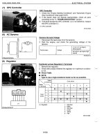
1) set the meter to read ohm's in the upper range, i.e. 1K, 10k or higher ohms.
2) disconnect the regulator so you can access the pins on the regulators connector.
3) place the meters + (red) lead on pin 1 and the - (black) lead on pin 5, you should read continuity. If it reads open the regulator is bad. It doesn't specify but lets assume for now that if you read any resistance that this step is good.
4) keeping the red lead on pin 1, move the black lead to pin 6, you should get the same reading as you did on pin 5.
5) skip pin 2
6) red lead on pin 3 and black led on pin 6 should read continuity. (same s previous tests).
-and so on.
Everytime I read electronics w/a multimeter, I'll switch the polarity of the meter's leads to make sure I'm not reading a dead short, so you'll want to do this at each step also. I say this because good diodes should only read continuity with the meters polarity set the correct way, in other words, it'll read good one way and open the other.
If the readings pass then it's safe to assume the regulator is good. If any one of the readings fail, the regulator can be assumed to be bad.
Good luck
Dave