planning rear hydraulics

/ planning rear hydraulics #1  

/pine

Super Star Member
Joined
Mar 4, 2009
Messages
15,763
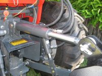
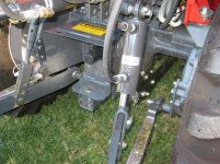
I am planning to put rear hydraulics on my tractor as well as top & tilt cylinders on the hitch...I am accumulating some parts while I wait out the winter...
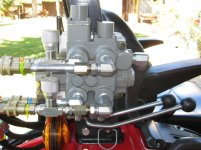
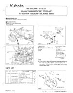
I have ordered the required outlet manifold kit from the dealer...this gets mounted behind the fenderso from there I have to hard plumb it for access at the rear of the tractor...

a few questions:

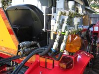
1.) should I plumb a set of QDC's (block 'T') before any valves? It seems to me this this would be for attachments like log splitters that have their own valve ?

2.) Besides the obvious...what are the pros/cons of using QDCs for the T&T cylinders over hard plumbing them into the valve body?

3.) Is there a particular brand of QDC I should look for? is there a type that can be attached under pressure? where is the best place to buy QDC's?

one more...As I said I was accumulating parts...I bought a Cross valve (on e-bay) for my T&T but I need the handle linkage...anyone know where to get just the links and pins? I don't need the handle or pivot cam...here is a link to a picture:
https://www.surpluscenter.com/item.asp?UID=2108011618084419&item=9-6654&catname=hydraulic
 
/ planning rear hydraulics #2  
1. Yes. Not sure what you mean by "block Tee" though, they would go either on the IN or the OUT side.

2. Absolutely use QD's on the work ports.

3. I used Pioneer couplers because that what JD uses, so all on mine match.
 
/ planning rear hydraulics #3  
(Quote)--I need the handle linkage...anyone know where to get just the links and pins?

Try the hardware store and try a #50 or larger master chain link. They well have the pin there also.
 
/ planning rear hydraulics
  • Thread Starter
#4  
Yes. Not sure what you mean by "block Tee" though, they would go either on the IN or the OUT side.

What I invisioned was the two lines from the outlet port piped to a "block tee" (machined "T") that can be bolted to infrastructure that is ported for two QDCs (no valves) with other ports to pipe to continue piping to control valves for the T & T +

??
 
/ planning rear hydraulics #5  
What I invisioned was the two lines from the outlet port piped to a "block tee" (machined "T") that can be bolted to infrastructure that is ported for two QDCs (no valves) with other ports to pipe to continue piping to control valves for the T & T +

??

Sounds complicated!
 
/ planning rear hydraulics
  • Thread Starter
#6  
Once I attach the outlet manifold see attached...

I hard pipe the lines to the rear of the tractor where I connect a set of QDC directly to these lines (using a "T") then continue piping the lines to a spool valve to control the T&T

I figured the "machined T" would give me something to mount to the tractor and make it convenient to access the QDCs ??

Is this not practical?
 

Attachments

  • 2-62001-outletblock.jpg
    2-62001-outletblock.jpg
    159.2 KB · Views: 242
/ planning rear hydraulics #7  
Once I attach the outlet manifold see attached...

I hard pipe the lines to the rear of the tractor where I connect a set of QDC directly to these lines (using a "T") then continue piping the lines to a spool valve to control the T&T

I figured the "machined T" would give me something to mount to the tractor and make it convenient to access the QDCs ??

Is this not practical?

Why have QDs before the spool valve? :confused: Usually the QDs would be at or after the valve work ports. Then the hoses that go to the "TnT".
Sorry, I am just not following what and why you're doing what you're doing. :confused: :eek:
 

Attachments

  • IMG_0145.JPG
    IMG_0145.JPG
    121.4 KB · Views: 258
  • IMG_0144.JPG
    IMG_0144.JPG
    127.2 KB · Views: 258
  • IMG_0142.JPG
    IMG_0142.JPG
    129.7 KB · Views: 253
  • IMG_0143.JPG
    IMG_0143.JPG
    134.6 KB · Views: 288
/ planning rear hydraulics
  • Thread Starter
#8  
This is why I am taking my time to plan it out...(I don't know what I'm doing)
Why have QDs before the spool valve?
my logic with a set of QDCs before the T&T valve is to plug in attachements like a log splitter that will have it's own valve...

An alternative would be to plumb the set of QDCs for the splitter after the T&T valve but what is the difference?... I can't see mounting a splitter valve (with detents) on the tractor...I want my splitter valve closer to the working side of the splitter...not mounted on the back of the tractor...

I am 100% open to suggestion and advice....
 
/ planning rear hydraulics #9  
my logic with a set of QDCs before the T&T valve is to plug in attachements like a log splitter that will have it's own valve...
You can get a valve that has detents, you could then use that valve for say the top link and your log splitter. Better yet, have a 3 spool valve and at least one of the valves would have detents for your log splitter.

I think that you are going to want QDs for your "TnT" hoses, at least for your top link anyway. Take a look at your tractor again, are you going to have enough room for all this stuff? All this plumbing and QDs take up a lot of room. :eek: I know that it does take a lot of planning to get stuff just right.
 
/ planning rear hydraulics #10  
Once I attach the outlet manifold see attached...

I hard pipe the lines to the rear of the tractor where I connect a set of QDC directly to these lines (using a "T") then continue piping the lines to a spool valve to control the T&T

I figured the "machined T" would give me something to mount to the tractor and make it convenient to access the QDCs ??

Is this not practical?

You can NOT Tee those lines from the manifold to the new valve.
 
/ planning rear hydraulics
  • Thread Starter
#11  
You can NOT Tee those lines from the manifold to the new valve.
OK

Pipe straight to the T&T valve and come of the PBYD of that valve for any additional remotes...

is there a reason not to hard pipe it from the manifold to the valve? or should I use a short length of hose to dampen any shock/vibration issues?
 
/ planning rear hydraulics #12  
OK

Pipe straight to the T&T valve and come of the PBYD of that valve for any additional remotes...

is there a reason not to hard pipe it from the manifold to the valve? or should I use a short length of hose to dampen any shock/vibration issues?

Correct, the new valve and ant additional valves (like on a logsplitter) need to be in series, The only acceptable place for a Tee is on the low pressure tank lines. Hydraulic fluid, like electricity will take the "path of least resistance", so if you Tee the high pressure lines fluid will just go through the other way.

Hard piping is fine, but not an easy job-it's also expensive. The steel pipe used for hydraulics is not easily bent into small places like where your manifold lives up to the new valve.
 
/ planning rear hydraulics
  • Thread Starter
#13  
Thanks for taking the time to explain things...

Is the (hydraulics) hard piping on a tractor not the same or similar to (SAE) brake lines ?

according to the instruction sheet (see post #6) for the outlet manifold it says the inlet/outlet ports are 1/4 18NPSF what size steel pipe would that be? I can work with 3/8 brake line fairly well...

Thanks again
 
/ planning rear hydraulics #14  
Thanks for taking the time to explain things...

Is the (hydraulics) hard piping on a tractor not the same or similar to (SAE) brake lines ?

according to the instruction sheet (see post #6) for the outlet manifold it says the inlet/outlet ports are 1/4 18NPSF what size steel pipe would that be? I can work with 3/8 brake line fairly well...

Thanks again
Are you thinking that you would use brake line material. :confused: Not quite the same, hydraulics are thousands of pounds of pressure. If you were to use brake lines, they would explode. :eek:
 
/ planning rear hydraulics
  • Thread Starter
#15  
Are you thinking that you would use brake line material
Actually I was just relating the process of bending and (double) flaring...

Is hydraulic tubing that much harder to work with than steel brake lines?

What size tubing would be standard to connect to the ports mentioned ( 1/4 18 npsf) ?
 
/ planning rear hydraulics #16  
/ planning rear hydraulics #17  
Some of the steel lines used for brake lines could be high pressure, but most people would not know the difference. If you don't know the difference, then get the steel line from qualified places. Then you have Stainless steel lines. You might see brake line pressure from about 800 psi to about 2000 psi. Who's to know.
 
/ planning rear hydraulics
  • Thread Starter
#18  
...Some of the steel lines used for brake lines could be high pressure...

most standard automotive tubing is seamed where "hydraulic" tubing is not...

I'm curious if my hand held benders will work with the thicker walled seamless tubing?

note: on the Kubota instruction sheet for the outlet manifold..it states 1/4 18NPSF...
1/4 seems small? what size tubing/hose will best to use?
 

Marketplace Items

1003 (A61166)
1003 (A61166)
John Deere 5045E for sale
John Deere 5045E...
2020 Kubota SVL75-2 (A60462)
2020 Kubota...
2015 VOLVO VNL SLEEPER (A59906)
2015 VOLVO VNL...
500 BBL FRAC TANK (A58214)
500 BBL FRAC TANK...
Giyi-D39 QA Trencher (A60463)
Giyi-D39 QA...
 
Top