Reading my JD-790 hydraulic schematic...

   / Reading my JD-790 hydraulic schematic... #21  
Sorry that the thread got hi-jacked like this!!Maybe ther is an admin that can help us out!!

Wayne County Hose said:
They told me that they are way more concerned with contaminants entering the pumps than getting into the tank. Stuff getting into the tank, via the breather or from added oil, is a much larger concern than contaminants entering the tank from the rest of the system. The machines over time have needed to be more compact and more powerful. There is only one way to accomplish both, more hydraulic pressure. The way they wanted to increase hydraulic pressure and efficiencies is by tightening up the tolerances. So now, those little particles in the air that enter through the breather everytime a cylinder is filled with oil are in the hydraulic oil. The old way, the oil had to circulate through the entire system until it got to the filter. By placing the filter in the suction side, they have the filtering they need with the tighter tolerances in the pumps, valves, and other components.
Thank you Wayne for commenting on this!!

Yes that make some sense. The scandinavian logging equipment industry, where I am from, have to deal with a lot of problems.....break downs in the middle of nowhere etc. I think refilling fluid and repairing hoses is the two biggest problems with keeping system clean...many system I worked with have had pressurized tank (1-2 psi pressure valve in breather filter), refill of fluid thru QC thru return filter, pumping direct from oil barrel, vacuum pump to limit spill when reparing hoses etc. Diesel powered engine heaters that also warm up the hydraulic liquid in the tank....But I have barely seen a suction strainer and never a suction filter with by-pass....probobly because I have been on the 63rd degree latitude with temps zubzero for 5 months a year...LOL..If you have to fire up a piece of logging equipment at minus 30, you might have to remove all strainers and filters out from the suction line.....

Anyway, this new way of thinking is interesting to hear....
I still wonder what the pressure setting is on that suction filter by-pass valve....can't be more than 1-2 psi.... ???
 
   / Reading my JD-790 hydraulic schematic... #22  
kennyd


Maybe you misunderstood what I was saying, and that is the return from the first valve or any valve should not go to the input of the next valve.

I know valves are hooked up in series all the time, and has nothing to do with what I said, when hooked up correctly, such as the out from the PB port to the input of the next valve.
 
   / Reading my JD-790 hydraulic schematic... #23  
AKKAMAAN ,

I do believe the cracking pressure on some suction filters are around 25 psi.

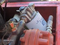
Below is the suction filter on the VSP/hydrostatic pump. It is 10 microns, with a bypass pressure of 25 psi.
 

Attachments

  • HPIM0100.JPG
    HPIM0100.JPG
    139.5 KB · Views: 214
   / Reading my JD-790 hydraulic schematic... #24  
Just to clarify, any return port on any valve will handle maximum system pressure. Placing valves in series is common. They use a system of priorities. A priority valve will port any fluid needed to the steering system. Then, pressurized fluid will travel to a valve powering let's say, your FEL's lift and curl systems. Then, pressurized fluid through to an accessory valve, maybe a grapple or whatever else. This is just on tractors now, which is such a drop in the ocean of hydraulic equipment overall.

Andy
 
   / Reading my JD-790 hydraulic schematic... #25  
Just to clarify, any return port on any valve will handle maximum system pressure. Placing valves in series is common. They use a system of priorities. A priority valve will port any fluid needed to the steering system. Then, pressurized fluid will travel to a valve powering let's say, your FEL's lift and curl systems. Then, pressurized fluid through to an accessory valve, maybe a grapple or whatever else. This is just on tractors now, which is such a drop in the ocean of hydraulic equipment overall.

Andy

As a matter of fact, that is how my Power-Trac works.

I believe what we are talking about is connecting a hose from the return port of a single lever valve with no PB, to the IN port of the next valve. Some say do it, I say not recommended. Just my opinion
 
   / Reading my JD-790 hydraulic schematic... #26  
As a matter of fact, that is how my Power-Trac works.

I believe what we are talking about is connecting a hose from the return port of a single lever valve with no PB, to the IN port of the next valve. Some say do it, I say not recommended. Just my opinion

They can try it, but unless the valve is made for power beyond, it won't work. I tried it.
 
   / Reading my JD-790 hydraulic schematic... #27  
AKKAMAAN ,

I do believe the cracking pressure on some suction filters are around 25 psi.

Below is the suction filter on the VSP/hydrostatic pump. It is 10 microns, with a bypass pressure of 25 psi.

Well, now it get real interesting.....Absolute Vacuum, AV, is about 15 psi under Atmospheric Pressure, AP, which means that AP is about 15 psi.
If tank have AP, then a 25 psi bypass valve will never open, because it impossible to get lower than 15psi under AP, which is AV. Cavitation probobly starts around 10 psi below AP.
 
   / Reading my JD-790 hydraulic schematic... #28  
Well, now it get real interesting.....Absolute Vacuum, AV, is about 15 psi under Atmospheric Pressure, AP, which means that AP is about 15 psi.
If tank have AP, then a 25 psi bypass valve will never open, because it impossible to get lower than 15psi under AP, which is AV. Cavitation probobly starts around 10 psi below AP.

Let me back up here, for a simple reason. Although the filter assembly on my system is used in a vacuum environment, and as such, how does the bypass work in a vacuum circuit. I understand about the cavitation in that you must prevent it from happening if possible. In my setup, a charge pump is drawing about 10 percent of the total volume for the VSP fluid via the suction filter to replenish fluid lost through the wheel motors, and to flush the VSP pump, and therefore add some cooling effect, and then the fluid goes to a radiator, and back to tank. The VSP and whee motor circuit is a closed loop system in that the fluid is circulating around the system, and fluid is only add as needed. So in the filtering process, the charge pump is sucking in fluid at a rate of about 5 to 7 GPM. and this process is used to filter the 20 gal reservoir about 15 times an hour. I believe the replacement on the filters is about 100 hrs.

Next question is, is that a vacuum gage or pressure gage on the filter body, or is there a vacuum bypass for the filter. Personally, I would like to see all three filters used, with a micron rating as low as 3 micron, on at least one of the pumps.
 
   / Reading my JD-790 hydraulic schematic... #29  
Any kind of gauge on the suction side is a vacuum gauge. The bypass on a suction filter works on the same principal as on the return side, just in reverse. The suction side bypass will pull the bypass valve open whereas the return side bypass pushes it open.
 
   / Reading my JD-790 hydraulic schematic... #30  
Wayne County Hose,

Thanks, I learn something everyday. Did not know that.

AKKAMAAN ,

Are you saying that if that filter has a 25 psi bypass that the pump will cavitate before it reaches the bypass rate? If that is true, I don't think very many people know that.
 

Tractor & Equipment Auctions

2015 Ford Transit 250 Cargo Van (A48081)
2015 Ford Transit...
3-Point Box Blade (A50860)
3-Point Box Blade...
2015 Top Hat T/A 20 ft. Gooseneck Trailer (A50860)
2015 Top Hat T/A...
2022 Ford F-550 Cab and Chassis Truck (A50323)
2022 Ford F-550...
2016 FORD TRANSIT 250 VAN (A51406)
2016 FORD TRANSIT...
2013 INTERNATIONAL PAYSTAR DAY CAB ROAD TRACTOR (A51406)
2013 INTERNATIONAL...
 
Top