Where is the "power beyond" port located on the CK10 series?

   / Where is the "power beyond" port located on the CK10 series? #1  

dieselfuelonly

Gold Member
Joined
Aug 13, 2007
Messages
332
Location
Chapel Hill, North Carolina
Tractor
Yanmar YM1401D
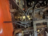
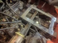
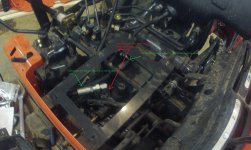
Trying to install the WR Long 3rd function kit on my CK2610. The instructions with the kit talk about removing a steel line that runs from the loader valve to under the seat, but don't provide any pictures or descriptions. I don't see any steel line running from the loader valve to under my seat, but there does appear to be this line that runs from under the seat to the valve body for both sets of rear remotes. Is this the right one?

7ZEWa8P.jpg
TctLnxx.jpg
L4gWcUp.jpg
 
   / Where is the "power beyond" port located on the CK10 series?
  • Thread Starter
#2  
Well I got impatient and took off the tire and fender and had a look for myself at what I believe is actually going on. Looks like the flow is:

Hydraulic pump -> Loader control valve -> Remote valve body -> Three point hitch valve

The remote valve body has a formed rubber hose that connects at a tee with the loader control valve which returns into the side of the transmission case.

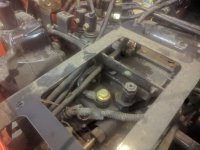
I removed the steel tube between the remote valve body (on the "T" side) and the three point hitch valve that is underneath the seat.

I ran the new hydraulic line with the 90* elbow fitting up to the "T" side of the remote valve body, and then connected it to the solenoid block. Then I ran the new hydraulic line with the straight fitting to the three point hitch valve and connected the other end to the solenoid block. Now the flow looks like this:

Hydraulic pump -> Loader control valve -> Remote valve body -> 3rd function valve -> Three point hitch

Everything *seems* to work, but I'm waiting on my root rake grapple to arrive before I can really test it.

3rdfunction.jpg
 
   / Where is the "power beyond" port located on the CK10 series? #3  
Trying to install the WR Long 3rd function kit on my CK2610. The instructions with the kit talk about removing a steel line that runs from the loader valve to under the seat, but don't provide any pictures or descriptions. I don't see any steel line running from the loader valve to under my seat, but there does appear to be this line that runs from under the seat to the valve body for both sets of rear remotes. Is this the right one?

First let me start by saying that the older CK series (that I have) and the newer CKxx10 Series (that you have) are slightly different in how they are plumbed and it may be that W.R. Long hasn't updated their instructions.

I found out about this difference trying to help another owner add additional rear remotes in this thread

https://www.tractorbynet.com/forums/hydraulics/404013-confirm-im-doing-right-adding.html

You should give it a look over because the hard line that you should be replacing is the same one he did. It goes from your loader valve to the rear of the tractor (In my case it went into the rear transmission housing, in your case based on what I learned from that thread, it should go to your rear remote valve stack).


Looks like the flow is:

Hydraulic pump -> Loader control valve -> Remote valve body -> Three point hitch valve

You are correct. On my older CK series the "->" between the Rear Remotes and the 3 Pt valve is internal to the rear end housing. I am thinking based on your pictures and the other thread I referenced that on the newer CKxx10 series this connection is now external via hoses / steel lines.

The remote valve body has a formed rubber hose that connects at a tee with the loader control valve which returns into the side of the transmission case.
This should be the "Return to Tank" line for both valves dumping everything to the common tank/sump on the tractor and you shouldn't have to do anything with this line / port

I removed the steel tube between the remote valve body (on the "T" side) and the three point hitch valve that is underneath the seat.

I ran the new hydraulic line with the 90* elbow fitting up to the "T" side of the remote valve body, and then connected it to the solenoid block. Then I ran the new hydraulic line with the straight fitting to the three point hitch valve and connected the other end to the solenoid block. Now the flow looks like this:

Hydraulic pump -> Loader control valve -> Remote valve body -> 3rd function valve -> Three point hitch

Everything *seems* to work, but I'm waiting on my root rake grapple to arrive before I can really test it.

Generally speaking in the hydraulic world, the 'T" or Tank ports are not meant for the same high system pressure as the rest of the system. however given your set-up where they have a steel hard line that supplies full system pressure to the 3pt then I think you'll be ok there. The 3rd function valve block is good because it's all milled from a single piece of aluminum thus the T port will take the same pressure as the P port and the work ports (A & B).


Just to be clear on flow path, The line from the "T" port above should be going to the "P" port on your solenoid block, and the "T" port on the solenoid block should be going to the 3pt.

Due to the nature of "Open Center" hydraulics, without the solenoid valve being activated, the 3pt will still work normally even if you have these reversed but the solenoid will be "backwards" (i.e. you energize for port A to have pressure and it will actually be Port B under pressure). I have no clue if this is "bad" but the logic for how a solenoid valve operates says it should be fine.


Typically the circuit is set-up like this instead.
Hydraulic pump -> Loader control valve -> 3rd function valve -> Remote valve body -> Three point hitch

I am by no means a hydraulic expert and I'm not as familiar with the specifics of your series tractor, but given what you have shared and with the provisions outlined above, I *THINK* you'll be ok.
 
   / Where is the "power beyond" port located on the CK10 series?
  • Thread Starter
#4  
N2DFire, thanks for your reply, when my grapple gets here I guess I'll find out! I'll report back with how it goes. Like you said, I think ideally the configuration would be Pump -> LCV -> 3rd function -> Remote -> TPH, however the space in between the LCV and the remote valve body is pretty tight and I'd have quite the excess of hose length to deal with. By locating the hoses between the remotes and the TPH the length worked out pretty much perfectly and there was a decent amount of room to work in. The instructions that came with the WR Long kit specifically mentioned the possibility of needing a different setup for the Kioti CK10s with a backhoe, meaning a remote valve body was in place. But all it was was a mention without any explanation, so who knows!

My guess is that CK10 tractors without the factory remotes have a hard steel line that goes straight from the factory LCV to the three point hitch valve located under the seat. I think that is where my initial confusion came from. Like you said usually the "T" port in most circumstances would be a low-pressure "return to tank" line, however on a small tractor like mine where the hydraulic system is basically just valves daisy-chained together in series the "P" side is the input and the "T" side is the output and the final destination to the tank is from the TPH valve. My guess is that the rubber line that runs from the remote valve body and tees in with the LCV and returns to the side of the transmission case is a path for the fluid to return to the tank if the relief valves open? Who knows.

I'm no hydraulic expert either - this is my first time really dealing with adding to a system as opposed to just changing out valve bodies or hoses. Only one way to find out if it works!!
 
   / Where is the "power beyond" port located on the CK10 series? #5  
Yeah the guy in that other thread was talking about how tight it was at the loader valve. After the struggles I went through building our 3rd function, I can't imagine it getting much tighter but apparently it did. lol

I built our 3rd function from scratch (I think I posted a copy of my write-up in that other thread) I did a LOT of reading & research here before I started, but it was still a major learning experience once the wrench turning started. lol

Hopefully yours goes well. Sounds like you have all the bases covered anyway.


What grapple did you get? You're going to love having one no matter whos. Mine stays on unless I specifically need the bucket or forks for something and then it's right back on when I'm done.
 
   / Where is the "power beyond" port located on the CK10 series? #6  
Where is the "power beyond" port located on the CK10 series?

N2DFire, thanks for your reply, when my grapple gets here I guess I'll find out! I'll report back with how it goes. Like you said, I think ideally the configuration would be Pump -> LCV -> 3rd function -> Remote -> TPH, however the space in between the LCV and the remote valve body is pretty tight and I'd have quite the excess of hose length to deal with. By locating the hoses between the remotes and the TPH the length worked out pretty much perfectly and there was a decent amount of room to work in. The instructions that came with the WR Long kit specifically mentioned the possibility of needing a different setup for the Kioti CK10s with a backhoe, meaning a remote valve body was in place. But all it was was a mention without any explanation, so who knows!

My guess is that CK10 tractors without the factory remotes have a hard steel line that goes straight from the factory LCV to the three point hitch valve located under the seat. I think that is where my initial confusion came from. Like you said usually the "T" port in most circumstances would be a low-pressure "return to tank" line, however on a small tractor like mine where the hydraulic system is basically just valves daisy-chained together in series the "P" side is the input and the "T" side is the output and the final destination to the tank is from the TPH valve. My guess is that the rubber line that runs from the remote valve body and tees in with the LCV and returns to the side of the transmission case is a path for the fluid to return to the tank if the relief valves open? Who knows.

I'm no hydraulic expert either - this is my first time really dealing with adding to a system as opposed to just changing out valve bodies or hoses. Only one way to find out if it works!!

I’m running into the same issue you encountered. Is the steel tube that you removed and hooked your third function to the right one? Did it work OK? There’s no way I could attach the hydraulic fitting to the rear remotes valve body and have clearance for the rear remote function levers.
 
Last edited:
   / Where is the "power beyond" port located on the CK10 series? #7  
Did your grapple function correctly? I followed your great photos and installed the same way. Now I’m just waiting for my grapple to arrive.
 
   / Where is the "power beyond" port located on the CK10 series? #8  
Did your grapple function correctly? I followed your great photos and installed the same way. Now I知 just waiting for my grapple to arrive.

Thank you - yes it worked perfectly. This is the right way to hook it up.
 
   / Where is the "power beyond" port located on the CK10 series? #9  
Hope you all gettin ur third function for your ck2610 's figured out. I built mine from scratch after quite a bit of research and hair pulling! I want to do a write-up on it to help out the next guy struggling with this cuz you can't just get the kit from kioti right now cuz of Covid of course. At least i couldn't find the kit from any kioti dealer i called and they acted like they were still waiting on parts from their supplier for several months.
 
 
Top