Weekend Repairs/check - Setting the valves

   / Weekend Repairs/check - Setting the valves #1  

RobJ

Elite Member
Joined
Jul 10, 2005
Messages
3,554
Location
Spring, TX (Houston)
Tractor
Kubota L2500
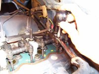
I pulled the valve cover this weekend to set the valves, took some pictures and thought I'd share what I found. Of the 6 valves I have, 5 were way loose, about double of spec. 1 was a little tight. My tractor has about 1200 hours and I bet it had never been done. No I couldn't tell if it ran better but it was closer to spec. The manual says to set it every 800 hours.

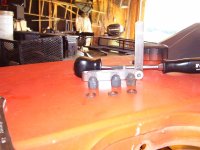
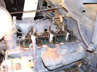
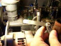
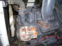
Setting valves not a biggie, I used a set of go,no-go feeler gauges. I removed the muffler for more work room. Valve cover comes off with 3 cap nuts, look for the copper washer. The valve cover gasket is an o-ring type set up, no sealer needed and the gasket was reusable. Since I used to do this I've set many of valves, and on the Kubota I only found 1 thing that can bit someone that wasn't watching closely. As I tightened with the gauges, the adjustment felt mushy. Since these are low revving engines, the valve springs are VERY weak. Not sure what the spec is but I could reach in with 2 fingers and press them down pretty easy. So slipping the feeler gauge to the NOGO part was actually openning the valves a bit giving me a false reading. I've never had this happen before. So setting with the gauges I had to lightly screw it down, then lock the screw. In hindsight, the go-nogo gauges were not the best thing. Because of the tight conditions, a set of dogleg feelers would have been the best. The spec for my tractor is .007-.009". I set them at .008". Turning the engine over is not a biggie, I can usually turn the fan and the belt is tight enough to roll the engine, just get the valves past overlay a quarter turn and set. The manual has a procedure for setting the, in 2 passes.. It's set the #1 on TDC, set #1 intake/exhaust, #2 Exhaust, #3 intake. Rotate the engine 360 degrees and set the others on #2 and #3. Ok now the question is which one is #1. Uhhh I haven't figured that out just yet. The manual says 1-2-3 starting "from the gear case side". That's a quote. So is that the tranny gear case side? Or the front cover gear case side. One day I'll check this out. In other engines I've worked on it would say "starting at the flywheel, or the front of the engine. If I had to flip a coin I'd say the one nearest the flywheel is #1. But I usually lose a 50/50 bet. :)

So some pictures.
 

Attachments

  • valve0.JPG
    valve0.JPG
    65.3 KB · Views: 369
  • valve1.JPG
    valve1.JPG
    78.9 KB · Views: 331
  • valve2.JPG
    valve2.JPG
    95.5 KB · Views: 314
  • valve3.JPG
    valve3.JPG
    65.7 KB · Views: 313
  • valve5.JPG
    valve5.JPG
    76.4 KB · Views: 301
  • valve6.JPG
    valve6.JPG
    92.3 KB · Views: 320
   / Weekend Repairs/check - Setting the valves #2  
I'll take the other 50 and gamble that #1 is the front towards the fan just like on a pickup truck engine.

Thanks so much for posting these pics and also posting them small enough to open quickly.
 
   / Weekend Repairs/check - Setting the valves
  • Thread Starter
#3  
Highbeam said:
I'll take the other 50 and gamble that #1 is the front towards the fan just like on a pickup truck engine.

Thanks so much for posting these pics and also posting them small enough to open quickly.


Well you win the bet. I went back to the PDF's and searched looking for more clues. Last one was a search on gear cover (what I would call the front cover) and that's what it is. The German diesels I worked on were from the flywheel, even the V engines.

no problem on the pictures, I found the tool on TBN last year to size them very quickly. If anyone else doesn't know look for it below...

Microsoft PowerToys for Windows XP

Rob
 
   / Weekend Repairs/check - Setting the valves #4  
I would have guessed as Highbeam did that #1 is nearest the radiator. Turning the engine over...mine had to be rotated same as normal engine rotation to find TDC and the amount to move off it. Does that make a difference in the way you had done it, now that you know #1 is up front? It seems if they were way out, you would se a noticeable difference in engine performance?
Rob-
 
   / Weekend Repairs/check - Setting the valves
  • Thread Starter
#5  
Actually Rob my new manual was in the house and I didn't want to dirty up the pages. :) Since it's only a small 3cyl I could mostly turn the engine over by pulling on the fan(plastic of course). Once I had to grab the front pulley. So I just went past overlap a turn and set them. If this was a big 6 or v8 I'd probably dont it differently.

No noticeable power change. A few were probably in the .020 range, now at .008. Seems like a lot but the main thing I noticed is a little less clatter. But it's back to spec now.

Rob
 
   / Weekend Repairs/check - Setting the valves #6  
RobJ said:
Ok now the question is which one is #1. Uhhh I haven't figured that out just yet.

When I adjust valves on cars or tractors, I just look at the cam lobes to
see if a valve is fully closed. There is no need to know the cylinder
numbers and go thru that "set #1 cylinder at TDC on the compression
stroke" process. I usually use a remote starter to turn the motor
a fractional revolution and set all the valves that are closed. Mark the
completed ones, bump the starter, repeat until done.
 
   / Weekend Repairs/check - Setting the valves #7  
The method of going one crankshaft turn past "overlap" (the point where exhaust is shutting and intake opening) is a good way but not ideal. Ideally, you would like to have the lifter on the cam directly opposite of the top of the lobe. That way you are sure to be on the 'base circle' of the cam. It is easy to do this--all you have to do is rotate the engine in the correct direction and watch the valves. When the exhaust valve just starts to open, that is the point of crankshaft rotation to set the intake. After setting that valve, keep turning in the same direction. When the intake valve has just shut completely, that is the point to set the exhaust. It's easy to see this if you draw the profiles of two cam lobes superimposed on each other, rotated roughly 90 degree such as most cams are. For chain drive cams, the exhaust is the lobe on the right. For gear drive, they switch.
 
   / Weekend Repairs/check - Setting the valves
  • Thread Starter
#8  
cp1969 said:
The method of going one crankshaft turn past "overlap" (the point where exhaust is shutting and intake opening) is a good way but not ideal. Ideally, you would like to have the lifter on the cam directly opposite of the top of the lobe. That way you are sure to be on the 'base circle' of the cam. It is easy to do this--all you have to do is rotate the engine in the correct direction and watch the valves. When the exhaust valve just starts to open, that is the point of crankshaft rotation to set the intake. After setting that valve, keep turning in the same direction. When the intake valve has just shut completely, that is the point to set the exhaust. It's easy to see this if you draw the profiles of two cam lobes superimposed on each other, rotated roughly 90 degree such as most cams are. For chain drive cams, the exhaust is the lobe on the right. For gear drive, they switch.


Really can't see the reason this is better. Once the valve closes and the engine turns another few degrees and the lifter is on the flat spot of the cam. There is no spot where the valve is slightly open after it closes until it starts to open again. Plus at overlap the piston is rounding TDC as the exhaust valve closes and the intake opens. Going another 360 is a safe bet your valves are nowhere near opening. But as mentioned you can set all the valves on any 4 stroke engine in 2 turns. On a 3cyl diesel TDC is hit (following the firing order) every 240 degrees. On the v12 it's every 60 degrees.

OK you got me on a v24 that is actually 2 v12's bolted together, have no idea how that sequence works, probably the same 2 turns though. :)

Rob
 
   / Weekend Repairs/check - Setting the valves #9  
Go to Comp Cams website, they can probably explain it way better than I can. I'm sure it's there. I read it out of their paper catalog, long ago. It has to do with the fact that the grind is only circular for that portion known as the base circle, and that is where the clearance is specified--with the lifter on the base circle of the cam. There are acceleration ramps built into other areas of the lobe. At TDC with both valves "closed", you are roughly 45 degrees of cam rotation (90 deg of crank) off from the ideal spot to set clearance for either valve.

It is probably more critical on engines with more radical cams, but nevertheless it is the right way to do it, assuming one wants to do it right in the first place. And it is no more trouble, so why not?
 
   / Weekend Repairs/check - Setting the valves
  • Thread Starter
#10  
CP, you'll have to find it for me. I'm always willing to learn new or better ways. I went to the web site and could not find those instructions. I did find other instructions on setting the valves they offer...seems most had to do with hydraulic lifters. But the section that covered the area basically said that it one valve is all the way down, then set the other valve. And IMO this does also work. But I've never heard of acceleration ramps in cams. If you can find it please pass it on.


From the Comp Cams web site..

Step 11: Install rocker arms. Do not tighten the adjusting nuts down before the proper sequence is performed. On engines with shaft mounted adjustable rocker arms, back off all adjusters completely before installing the assembly. Make sure the pushrod is in the lifter and the rocker arm seat when making valve adjustments.

Hydraulic Flat Tappet and Hydraulic Roller Camshaft: First turn the engine in the normal direction of rotation. Start with cylinder number one (1). When the exhaust valve begins to move, adjust the intake valve to zero lash plus an additional ½ turn more. Rotate the engine over again until the intake valve reaches maximum lift and is almost all the way back down. Then set the exhaust valve to zero lash plus ½ turn. Adjust the valves on each cylinder in this manner until all valves are adjusted. If the engine has nonadjustable rocker arms, a lifter preload of .020” to .040” must be aintained. See “Non-Adjustable Rocker Arms” section for proper preload instructions.

Mechanical (Solid) Flat Tappet and Solid Roller Camshafts: Follow the same adjustment procedure. Instead of lifter pre-load, use the prescribed valve lash clearance found on the cam specification card. If you have misplaced your cam spec card call COMP Cams® CAM HELP® line
at 1-800-999-0853 for the proper valve lash clearance. Mechanical valve lash adjustment is recommended at every oil change.
 

Tractor & Equipment Auctions

2025 AllMetal K0720 UNUSED 20 ft. Bi-Parting Metal (A50860)
2025 AllMetal...
2025 Kivel 48in Forks and Frame Skid Steer Attachment (A50322)
2025 Kivel 48in...
2023 Ford Explorer AWD Hybrid SUV (A48082)
2023 Ford Explorer...
Skid Steer Fork Attatchment (A50860)
Skid Steer Fork...
Pallet of Propane Burners (A50860)
Pallet of Propane...
2013 Chevrolet Impala Sedan (A48082)
2013 Chevrolet...
 
Top