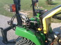
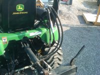
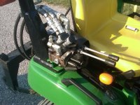
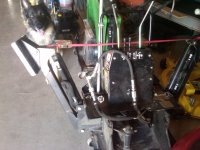
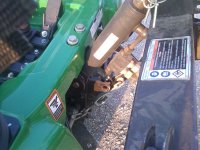
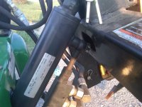
Parts and information list:
INFORMATION:
1. What I have going on here is a bit "off campus". Someone may not understand the plumbing, in the absence of HYD experience. Allow me to explain.
Lets go over the plumbing.
For explanation I will refer to pressure and flow as power?
1. I used a valve that can be configured for OPEN or CLOSED center. This means either the power flows thru the valve or stops at the valve (more or less). Because we want to operate the BH AND the VALVE a switchable valve turns out to be important.
2. In the configuration I use the valve is CLOSED CENTER! Now, before everyone freeks because the tractor needs OPEN center, we must think about what is going on here. Again, we want the VALVE AND the BH at the same time. This makes things a bit different than if we were just adding a valve without the BH.
3. The valve in question has the option (WHEN IN CLOSED OPERATION) to pass the power thru the valve and continue it on. That is EXACTLY what we are looking for in order to have the BH AND the valve at the same time option.
4. We CLOSE the valve (install the set screw inside to block off) in order to turn on this pass thru of the power?
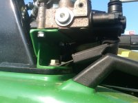
5. In one of my previous pictures you can see the valve with a fitting connected to a port marked P. This is the power coming from the tractor side. Now, normally when the BH is not involved this power just flows thru the valve in a straight forward way. We need that power to be in the valve AND continue on to the BH. Regardless, make note the power is incoming from the tractor to the P port on the valve.
6. Because we have configured the valve CLOSED the port used to return the power to the tractor no longer works. This is sort of a problem, we have all this power from the tractor and it needs someplace to go. The outlet port on the valve no longer works.
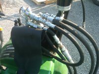
7. Because we have a CLOSED valve, the extra power port is now enabled. This means that the power is now not going to the return port, it is going to the extra power outlet. This is the LOOP you see in the pictures. The side of the loop NOT having the quick disconnect is the side the power is coming from.
8. Now given #7 we can possibly begin to see what is going on here. We see that I have a T fitting connected to the standard return port on the valve. However, I have previously stated this port is dead by configuring the valve to be CLOSED.
9. When we think about #8 we go WTF? The valve is closed why on earth did this ****** Sean plug fluid into it? Well, because I need something to hold things in place

The default outlet port is being used to connect / hold other lines and fittings in place BUT IT IS NOT OPERATIONAL! Again, the VALVE IS CLOSED! Remember I said the power is now in the loop you see headed for the large quick disconnect that sits on top of the valve. This is due in part to the restrictions on space that exist with the swivel seat. We cant have a bunch of stuff extending out of the valve in the direction of the seat.
10. Now when we continue to look at the T connection we see the last outlet on the T we have NOT already discussed is directed back to the tractor (this is the power return).
11. The loop is now emulating the factory power beyond loop with nothing connected to it. This power needs a place to go when in operation (open center systems). This is why it plugs back into the T that is returning fluid to the tractor sump.
12. Now when the BH is required the loop is disconnected and the BH is connected to the fitting at the top of the T and the female quick disconnect shown on top of the valve in the pictures. Thus, when the BH is connected power flows thru the system just as if the valve was not there. HOWEVER, because the valve is inline it can use the power to do work at the same time the BH is in operation. Disconnecting the valve is not required. When the BH is not attached, the loop is simply connected to the top of the valve (drain / return) and we have an operational valve and no BH.
Again, the BIG thing/s to note here are:
1. THE VALVE IS IN CLOSED OPERATION!
2. THE VALVE RETURN PORT IS BLOCKED! This is why the T is REQUIRED! The T becomes the path for the power to return to the tractor.
3. The T is installed for the purpose of holding the return line to the valve and providing a place to put a quick connect for the BH return. There is no power flowing out the bottom connection of the T that is attached to the valve.
This picture helps illustrate the concept:
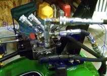
I can fill in more information about the setup as required. I do assure you it has been working just fine for over a year now.
Ok,
Parts list:
QTY is shown (?)
Numbers in [??] represent the fitting angle not the seal angle.
1. JD 2305 TLB (1)
2. PRINCE / Wolverine [ MB21BB5C1 ] valve. (1)
BH SIDE STUFF:
1. LINE 22 inch long 3/4 NPT MALE -> 1/2 NPT MALE (1)
2. 3/4 NPT MALE -> 1/2 NPT swivel [45deg] (1)
3. 1/2 FEMALE O-RING -> 3/4 NPT FEMALE (1)
4. 3/4 NPT FEMALE -> 1/2 MALE O-RING [90deg] (1)
5. 1/2 MALE O-RING -> 37deg MALE (factory BH connect) (1)
TRACTOR SIDE STUFF:
1. Caps for 1/4 quick disconnect (get from JD) (4)
2. 2 x 1/8 x 12 steel angle (bracket) TSC (1)
3. 1/4 FEMALE quick disconnects (TSC) (4)
4. 1/2 MALE O-RING -> 1/2 FEMALE NPT [90deg] (1)
5. 1/2 MALE NPT -> 1/2 FEMALE NPT swivel [45deg] (1)
6. LINE 20.5 inch long 1/2 NPT MALE -> 1/2 NPT FEMALE (1)
7. 1/2 NPT MALE -> 1/2 NPT FEMALE [90deg] (1)
8. 1/2 NPT MALE -> 37deg FEMALE swivel (1)
9. 1/2 37deg MALE -> 1/2 MALE O-RING (1)
10. BH size / Large FEMALE coupler (2)
11. 1/2 MALE O-RING -> 1/2 FEMALE swivel (1)
12. LINE 7.5 inch long 1/2 MALE NPT -> 1/2 MALE NPT (1)
13. 1/2 FEMALE NPT -> 3/4 FEMALE NPT swivel (1)
14. 1/2 FEMALE swivel 37deg -> 1/2 FEMALE swivel 37deg -> 3/4 NPT MALE T fitting. The 3/4 must be the MID T connection
15. 1/2 MALE O-RING -> 1/2 MALE 37deg (1)
16. 1/2 MALE 37deg -> 1/2 MALE O-RING [90deg] (1)
17. BH size / large MALE coupler (1)
18. LINE 26 inch long 1/2 MALE NPT -> 1/2 MALE NPT (1)
19. 1/2 MALE O-RING -> 1/2 FEMALE NPT [90deg] (1)
20. 1/2 NPT FEMALE -> 1/2 NPT FEMALE swivel (CCM link connection fittings). (2)
21. LINES 36 inch long 1/2 MALE NPT -> 1/2 MALE NPT (2)
22. 1/2 MALE O-RING -> 1/4 MALE 37deg [45deg] (4)
23. 1/4 NPT MALE -> 1/4 FEMALE 37deg swivel (4)
24. 1/2 NPT FEMALE NPT swivel -> 1/4 MALE 37deg (2)
25. 1/4 FEMALE swivel 37deg -> 1/4 MALE NPT [45deg] (2)
26. 1/4 MALE coupler (2)
27. LOCTITE 545 <- IMPORTANT!
Hit me up with any questions you have.
I had to do the parts list myself off the tractor. My guy at the HYD place went off and retired on me. The replacement is not "helpful"...
Some warning about cost, they are REALLY proud of this HYD "stuff". Nothing on that list (other than the caps) is less than 5 bucks. The valve set me back about 130, the top link 180ish (IIRC), the fittings and stuff were more than the valve and the top link together. There are several areas where a person could just use a line and not have quick disconnects in place. Mainly the power beyond connections to the valve. I elected to use / pay for the disconnects so I could very quickly isolate / remove the valve as desired. If something valve side gives up the ghost at a work-site I can be back digging in a very short time by unplugging the valve and swapping the quick connects on the BH. Money could be saved however if straight lines were used in place of all the quick connect stuff coming from the tractor power beyond.
A person doesn't have to swap the BH connectors. I did so to prevent the peeing that female connectors are good for from leaking all over the tractor. I can drain the fluid from the female connector when I connect the BH.
Best regards,
Sean
