You are using an out of date browser. It may not display this or other websites correctly.
You should upgrade or use an alternative browser.
You should upgrade or use an alternative browser.
Rear Blade Rear Blade for JD 5303
- Thread starter deere5105
- Start date
- Views: 22369
-
- Tags
- john deere 5303
More options
Who Replied?
/ Rear Blade for JD 5303
#61


OP
deere5105
Veteran Member
- Joined
- May 6, 2009
- Messages
- 1,086
- Location
- South Mississippi
- Tractor
- 2008 John Deere 5303 MFWD, 2004 John Deere 5205
LD1 said:IF you are interested in hearing how I would do the re-enforcement, here goes...
<img src="http://www.tractorbynet.com/forums/attachment.php?attachmentid=284636"/>
this supports the blade itself. This is the strongback. Dont have to be super heavy duty. Its the added depth that gives strength. 1/8" plate would be sufficient. Or could use a piece of 5" channel iron or something and then cut the triangles for top and bottom.
This is how I would strengthen the A-frame:
<img src="http://www.tractorbynet.com/forums/attachment.php?attachmentid=284637"/>
Box in the underside of the horizontal. This will increase the strength in the horizontal (pulling direction) significantly. And also prevent bees.
The gussets will help prevent bending in the vertical direction like it has already been bent.
This is what I would do if the blade were mine. Materials to be used and design of it would all be dependent on what I have in the scrap pile. But even if you had to buy new steel, AND have it cut/sheared to your dimensions (triangles and such) I dont see it being more than $100 worth. And this would significantly strengthen the blade. The only last weak link would be the pivot pin diameter, and the category 1 hitch set-up. But I dont think any of that would be a big issue.
Also, if it has not been done, one other thing I would do...that triangular box u-shape piece where the TL hooks up....that entire vertical section, if it isnt welded solid to the main beam...I would do so.
Again, this is just what I would do if it were mine. It would take maybe half a day at most with just a set of torches and a welder and digging through the scrap pile. But YMMV as always.
There more I look at these pictures the more I like these suggestions. Seem to be fairly simple steps to build and simple strengthening logic.
If boxing in the bottom of the horizontal piece where the lift pins are, how do I get back to the lift pin nut to replace the pins if they need replacing? (Believe it was Jenkins that warned, but I did wind up bending one on my 8' 3PT disc harrow. Went with Cat 1 pins to be able to swap to another tractor if needed.)
The cutting edge is worn, unevenly. It is welded on versus bolted. Think I would rather replace and bolt on to make it easier to rotate or replace in future. Any warnings or suggestions on that?
LD1
Epic Contributor
I guess you could leave an access hole to get to the nut. Usually, when something like that is boxed in, the heavy plate on the end that the pin is bolted to is either threaded or has a nut welded on the back so it isnt an issue.
As to the cutting edge, if you could, it would be best to remove the old. And then if you want to bolt on a new one, drill the holes and do so. But I would NOT try to mount over the existing cutting edge. They are pretty hard and make for sme tough drilling. You would most likely spend less time with a grinder and slicer disk and take off the old edge.
As to the cutting edge, if you could, it would be best to remove the old. And then if you want to bolt on a new one, drill the holes and do so. But I would NOT try to mount over the existing cutting edge. They are pretty hard and make for sme tough drilling. You would most likely spend less time with a grinder and slicer disk and take off the old edge.
IMO This vvvv is stronger.....and just as easy to do.....
View attachment 284679View attachment 284680View attachment 284681
It would be harder to make but you could use a wide piece of channel.
OP
deere5105
Veteran Member
- Joined
- May 6, 2009
- Messages
- 1,086
- Location
- South Mississippi
- Tractor
- 2008 John Deere 5303 MFWD, 2004 John Deere 5205
LD1 said:I guess you could leave an access hole to get to the nut. Usually, when something like that is boxed in, the heavy plate on the end that the pin is bolted to is either threaded or has a nut welded on the back so it isnt an issue.
As to the cutting edge, if you could, it would be best to remove the old. And then if you want to bolt on a new one, drill the holes and do so. But I would NOT try to mount over the existing cutting edge. They are pretty hard and make for sme tough drilling. You would most likely spend less time with a grinder and slicer disk and take off the old edge.
Guess the concern is that the Cat 1 pins would be a weak link, but cheap and easy to replace. The welded nut would be an option. I was thinking of having room to get to the nut to be able to position the pin holes vertical and then tighten.
The guy that does my welding builds the bionic blades and uses some used road grader blades for the cutting edges. Was thinking along the lines of removing existing cutting edge and replacing with one of those if available. By bolting it on, if wear starting to show could unbolt and flip for new edge.
jenkinsph
Super Star Member
I would remove the old blade and bolt on the replacement as you mention.
I looked thru my scrap pile and found two lengths of box tubing one was 3x6x1/4" rectangular box tubing and the other was 4x6x1/4" after looking at this it appears that a 3' length of the 4x6 box tubing will make two tapered pieces that are 32" in length, just a little torch work. I am having trouble with my camera but will work on this and post pictures over the next few days. This does eliminate the chance of moving the blade off center but I have been leary of this being a good idea anyway. That is why I thought of making it offset while I am at it.
Looking at copying the Landpride method with the tapered braces. Thanks for the pictures LD1
OP
deere5105
Veteran Member
- Joined
- May 6, 2009
- Messages
- 1,086
- Location
- South Mississippi
- Tractor
- 2008 John Deere 5303 MFWD, 2004 John Deere 5205
jenkinsph said:I would remove the old blade and bolt on the replacement as you mention.
I looked thru my scrap pile and found two lengths of box tubing one was 3x6x1/4" rectangular box tubing and the other was 4x6x1/4" after looking at this it appears that a 3' length of the 4x6 box tubing will make two tapered pieces that are 32" in length, just a little torch work. I am having trouble with my camera but will work on this and post pictures over the next few days. This does eliminate the chance of moving the blade off center but I have been leary of this being a good idea anyway. That is why I thought of making it offset while I am at it.
Looking at copying the Landpride method with the tapered braces. Thanks for the pictures LD1
Will be curious to see how your project progresses and how satisfied you are when finished. I assume with the box tubing you would only have to cut the one angle that fits against the moldboard and then a short rectangular piece to close the taller open end and your done. By adding this, I believe you mentioned it eliminates the ability to offset the blade?? I too would be a little concerned over putting the extra stress on the moldboard. Can/will you photograph your steps as you go?
jenkinsph
Super Star Member
deere 5105,
I plan on pictures if I can get the camera to work. I will add the stongbacks to the moldboard first, that is pretty much figured out. I am more concerned now with making the main beam offset working on that issue right now.
I plan on pictures if I can get the camera to work. I will add the stongbacks to the moldboard first, that is pretty much figured out. I am more concerned now with making the main beam offset working on that issue right now.
OP
deere5105
Veteran Member
- Joined
- May 6, 2009
- Messages
- 1,086
- Location
- South Mississippi
- Tractor
- 2008 John Deere 5303 MFWD, 2004 John Deere 5205
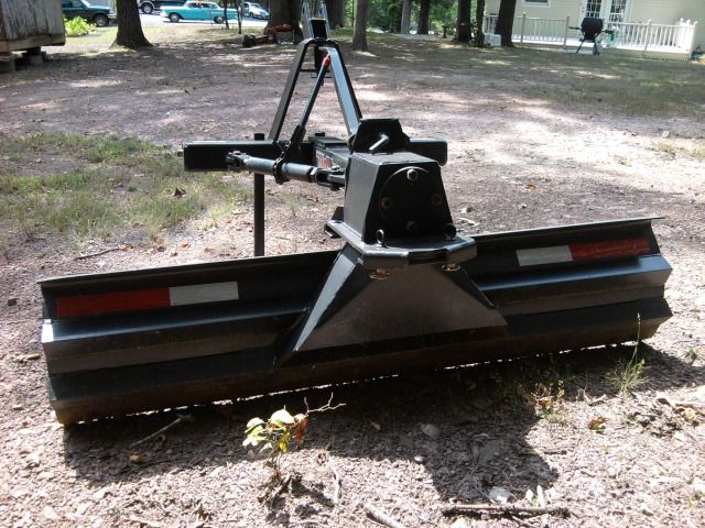
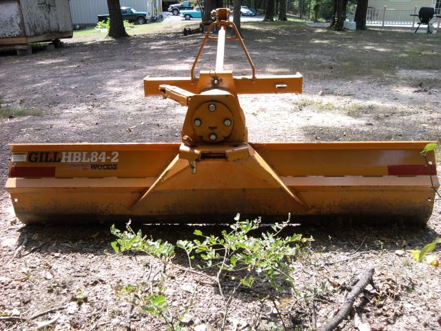
Got it hooked up and made a few passes along the drive. Really like being able to grab rocks on the edge and roll them back away from the grass to the center of drive. Was able to tilt by adjusting 3pt hitch while angled. First time ever using this type blade.
I do believe the bottom has been pulled back some, but didn't seem to cause any negative, noticeable issues. What am I missing? What issues will occur because of this?


I do believe the bottom has been pulled back some, but didn't seem to cause any negative, noticeable issues. What am I missing? What issues will occur because of this?
deere5105 said:Got it hooked up and made a few passes along the drive. Really like being able to grab rocks on the edge and roll them back away from the grass to the center of drive. Was able to tilt by adjusting 3pt hitch while angled. First time ever using this type blade.
I do believe the bottom has been pulled back some, but didn't seem to cause any negative, noticeable issues. What am I missing? What issues will occur because of this?
<img src="http://www.tractorbynet.com/forums/attachment.php?attachmentid=284783"/>
<img src="http://www.tractorbynet.com/forums/attachment.php?attachmentid=284784"/>
<img src="http://www.tractorbynet.com/forums/attachment.php?attachmentid=284785"/>
<img src="http://www.tractorbynet.com/forums/attachment.php?attachmentid=284786"/>
It looks like to me the top edge is tweaked foward on both sides. Since the moldboard has been bent it is probably weaker than what it would normally be.