Pto driven water pump

   / Pto driven water pump #11  
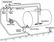
The roller pump is a positive displacement device. That is ... if you dead head or block the flow, something has to give. Either a relief valve or pressure regulator. If you don't allow for over pressure, it will be expensive or dangerous or both.

usually a pressure regulator is used with the excess flow going back to the tank. The diagram you posted does not have any relief valve shown. The system as shown is dangerous. Close the agitator valve and the boom valves = dead headed system.
 
   / Pto driven water pump
  • Thread Starter
#12  
Thank you. I found a better diagram that reflects what you wrote : I'm hoping the pressure relief valves aren't as expensive as what I have found so far..
 

Attachments

  • image-1581433572.jpg
    image-1581433572.jpg
    78.6 KB · Views: 10,453
   / Pto driven water pump #13  
Relief valves are simple & cheap. Besides pressure rating you must size it for the max volume of the pump. Example: A 2 gpm relief valve on a 200 gpm pump isn't much protection. Even when relieving, that system will build pressure at the rate of 198 gpm
 
   / Pto driven water pump
  • Thread Starter
#14  
Relief valves are simple & cheap. Besides pressure rating you must size it for the max volume of the pump. Example: A 2 gpm relief valve on a 200 gpm pump isn't much protection. Even when relieving, that system will build pressure at the rate of 198 gpm

So for a http://bit.ly/1oTApFppump rated max 19.6 gpm would you attach a 20 gpm relief or would you go lower?
Btw thanks
 
   / Pto driven water pump #15  
If the pump will produce 19.6 gpm at 540 rpm, And you're going to run it at 540 RPM then I would install the 20 gpm relief valve. Use large enough pipe to carry the 20 gpm too ... You do not want to reduce it to 1/4 inch tubing lol !

Remember, a relief valve is held closed by a spring. When the pressure is more than the spring can hold, the valve opens. When the pressure falls below the set point, the valve will close. Some relief valves are adjustable, others are permanently set at the factory.

It's the fluid equal to a circuit breaker.
 
   / Pto driven water pump
  • Thread Starter
#16  
If the pump will produce 19.6 gpm at 540 rpm, And you're going to run it at 540 RPM then I would install the 20 gpm relief valve. Use large enough pipe to carry the 20 gpm too ... You do not want to reduce it to 1/4 inch tubing lol ! Remember, a relief valve is held closed by a spring. When the pressure is more than the spring can hold, the valve opens. When the pressure falls below the set point, the valve will close. Some relief valves are adjustable, others are permanently set at the factory. It's the fluid equal to a circuit breaker.
Awesome and good point about the return size pipe size. I've been reading a lot it seems -about something as simple as this - I appreciate the help . I've tried Google eBay CL just to get an idea of price and I think I found a few (been seeing a lot of different kinds) but pricing is over 50 which makes me think I haven't been either looking in the right place or Im being overly cautious - I've been trying to understand if they are rated by gpm or psi when I read your last response. Things come together quickly with the help of this forum so I'm going to keep on looking maybe to find some more options I'm thinking it would be easier to find it online rather than ace or some other place but if you or anyone has any experience buying one at a good price (or say around 20$) let me know .. ok ramblin on here thanks
 
   / Pto driven water pump #17  
Since you're building a sprayer... you might check what regulator is used on sprayers. My sprayer has a regulator that relieves excess flow back to the tank.... combining regulator & relief functions into one unit for less cost.
 
   / Pto driven water pump #18  
Here's my home built sprayer. Pump is a Silver Series 6 roller Hypro, PTO driven. Suction and discharge from the pump is 3/4" hose, plastic manifold piping, solenoid valves, and relief valve and discharge hose are 3/4" ID. The relief discharge continues to the bottom of the tank and functions as an agitator, keeping the solution mixed. The boom and wand are fed with 3/8" hose. The flood tips I use spec a recommended pressure of 40#, @ 20" above the plant. To achieve this pressure, I start the pump running with the valves closed and adjust the relief to about 44#. When the valve to the boom is opened, the pressure levels out at 40#. When using the wand I adjust the pressure to get the distance of spray I want. Here's a link to the relief valve, it was a little cheaper a couple of years ago. Hamilton Pressure Regulating Bypass Valve, Nylon, 3/4 in. MNPT Inlet x 3/4 in. FNPT - Tractor Supply Co. . The second picture shows the distance sprayer will reach when the wand is dialed down to a stream. About 40'. Mark


   / Pto driven water pump
  • Thread Starter
#19  
Here's my home built sprayer. Pump is a Silver Series 6 roller Hypro, PTO driven. Suction and discharge from the pump is 3/4" hose, plastic manifold piping, solenoid valves, and relief valve and discharge hose are 3/4" ID. The relief discharge continues to the bottom of the tank and functions as an agitator, keeping the solution mixed. The boom and wand are fed with 3/8" hose. The flood tips I use spec a recommended pressure of 40#, @ 20" above the plant. To achieve this pressure, I start the pump running with the valves closed and adjust the relief to about 44#. When the valve to the boom is opened, the pressure levels out at 40#. When using the wand I adjust the pressure to get the distance of spray I want. Here's a link to the relief valve, it was a little cheaper a couple of years ago. Hamilton Pressure Regulating Bypass Valve, Nylon, 3/4 in. MNPT Inlet x 3/4 in. FNPT - Tractor Supply Co. . The second picture shows the distance sprayer will reach when the wand is dialed down to a stream. About 40'. Mark http://s971.photobucket.com/user/briarhhillbrittanys/media/Sprayer003.jpg.html http://s971.photobucket.com/user/briarhhillbrittanys/media/Sprayer008.jpg.html

So many thanks for that link I have been looking and to no avail..

I found those other pictures - the plumbing diagram.. here
Homebuiltsprayerplumbing.jpg
now the question i have is - are the pressure gauge and the pressure relief valve plumbed oppositely.. that after the roller pump comes the relief? so the series is:
tank - strainer - PUMP - pressure relief - solenoid (to sprayer) -solenoid (to boom) - guage

lost a bit if thats not the case and.. the solenoids.. they're plumbed by a 'T' fitting.. and the outlet of each solenoid is where the hose drops from 3/4 to 3/8 line
?
I found this picture after that one..so i'm editing this to throw it in.. must have been version before the above one.. so that as long as the relief and gauge go before the ball valve (or solenoid in your case) we can see the pressure that will be going to the sprayers.. and all plumbs well. got it.

BoomSprayer002.jpg
Btw that is an awesome setup you have there and nice looking mature trees and greenery.
DB
 
Last edited:

Tractor & Equipment Auctions

2021 Caterpillar 303 CR (A44501)
2021 Caterpillar...
2017 Club Car Precedent Golf Cart (A44789)
2017 Club Car...
2006 STERLING  L9500 MIXER (A45046)
2006 STERLING...
2007 KENWORTH T300 SERVICE TRUCK (A45333)
2007 KENWORTH T300...
2009 Ford Flex SUV (A42744)
2009 Ford Flex SUV...
2019 Harley Davidson FLHTP Electra Glide Motorcycle (A42744)
2019 Harley...
 
Top