New version of Pat's Easy Change

   / New version of Pat's Easy Change #1  

Bob_Skurka

Super Member
Joined
Jul 1, 2003
Messages
7,615
New version of Pat\'s Easy Change

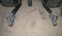
I just got and installed the Pat's Easy Change system on the lower links. I have not tried it yet. It appears to be very well made but some nuts supplied are very soft steel and are not of the locking type. I will probably upgrade to better quality locking nuts as soon as I get time to run to the hardware store. The instructions were pretty sparce, and did not describe what to do with the hex screws that are on the sides of the Easy Change system. Fortunately, it looks like something that only requires half-a-brain to install, and since my wife says I only have half-a-brain, I did figure it out.

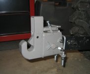
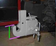
This is a side view of one of the Easy Change pieces.
 
   / New version of Pat's Easy Change
  • Thread Starter
#2  
Re: New version of Pat\'s Easy Change

Oops, the picture did not post on my first try. But this picture, if it attaches, it a top view of both lower arms.
 

Attachments

  • 323065-pats top.jpg
    323065-pats top.jpg
    89.1 KB · Views: 5,341
   / New version of Pat's Easy Change
  • Thread Starter
#3  
Re: New version of Pat\'s Easy Change

Here is a view of the side of one of the lower arm attachment points.
 

Attachments

  • 323068-pat\'s side.jpg
    323068-pat\'s side.jpg
    77.9 KB · Views: 4,239
   / New version of Pat's Easy Change #4  
Re: New version of Pat\'s Easy Change

Bob,
What is the purpose of the 2 bolts sticking through the sides?
I understand everything but those........

Jerry
 
   / New version of Pat's Easy Change
  • Thread Starter
#5  
Re: New version of Pat\'s Easy Change

Jerry,
That part is NOT explained at all in the instructions, so that is where the half-a-brain had to kick in and do some thinking. Originally I thought that they were there just to hold the Easy Change system steady, but the more I looked at it, if I used the 4 hex screws/bolts (2 are located on each side) to clamp it into place then the unit would sit at a slight angle. SO USING MY THINKING CAP, I came to the conclusion that their puropose is to LEVEL the Easy Change system so that the bottom of the hook is parallel to the ground. By adjusting them you can level the unit so it will meet the implement pins squarely and not cause uneven wear or rubbing. At least that is what I think. But you got to realize, I sell candy to children for a living so that doesn't take too much brain power to do so I might be wrong on what the 4 hex screws/bolts are used for.
 
   / New version of Pat's Easy Change #6  
Re: New version of Pat\'s Easy Change

Bob,

The instructions could be a little better. I made the same discovery when I installed mine a few weeks ago.

The screws are used, at least by me, to adjust the angle at wich the adaptor meets the lower pins. They allow adjustment in two planes that maximizes adaptor to pin contact.

It's true however that if you have implements with a great variation in pin spacing there will be times when full contact can't be achieved without making an adjustment. My three current implements are pretty close in spacing so it's not an issue.

Did you have to use any spacers? On my JD 4100 I used one on each side. It wasn't until the second side that I realized I could install the roll pin in the spacer and drop it in place before sliding the adaptor on.

Sure is nice not to have to wrestle the ball ends over the pins though.
 
   / New version of Pat's Easy Change
  • Thread Starter
#7  
Re: New version of Pat\'s Easy Change

Gary,
What you wrote is what I was trying to say. They are used to maximize contact with the implement pins . . .
 
   / New version of Pat's Easy Change #8  
Re: New version of Pat\'s Easy Change

Bob: What is the distance between the top and bottom of the "J"? (see green line in attached). In other words how much clearance do you need between the bottom of the pins on your implement and any obstructions on the implement?
 

Attachments

  • 323187-Pats link adapter.jpg
    323187-Pats link adapter.jpg
    7.8 KB · Views: 2,403
   / New version of Pat's Easy Change
  • Thread Starter
#9  
Re: New version of Pat\'s Easy Change

The tractor is at home and I'm at work, but I would estimate the length of the line on your attached photo at a little over 2 inches.

The 3 implements I have to attach to have no obstruction issues on the implements themselves, although I do have the PHD laying on the ground and I think I may need to rig up something to hold it up off the ground because the way I lay it down, the lower link pins are flush to the ground. I suspect a couple cement blocks would solve the problem and I could back right under the pins and lift the hydraulics.
 
   / New version of Pat's Easy Change #10  
Re: New version of Pat\'s Easy Change

Thanks, Bob. I have a rototiller that may have a clearance issue with its support structure...
 

Tractor & Equipment Auctions

Adams 8 Ton Weigh Hopper (A50397)
Adams 8 Ton Weigh...
12-UNUSED LANDHONOR 25" X 185MM UNIVERSAL BKT PINS (A50460)
12-UNUSED...
HOWSE ES24 DIRT SCOOP (A50459)
HOWSE ES24 DIRT...
Airco Tig Welder (A49346)
Airco Tig Welder...
FLOWTRONEX SYRINGE FAN (A50460)
FLOWTRONEX SYRINGE...
2020 CATERPILLAR 259D3 SKID STEER (A50458)
2020 CATERPILLAR...
 
Top