I have a late 90s model 7275 cub cadet tractor and the turn signals did not work. One of the tail lights was on constantly and the other turn signal light wouldn’t turn on at all. The red tail light in the back also wouldn’t light
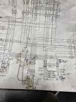
Searched online for schematic and found something close enough. The turn signal and hazard lights use a electronic control box called a hazard unit but is no longer available. They also wanted close to $500 when it was available so it wasn’t really a option.
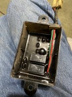
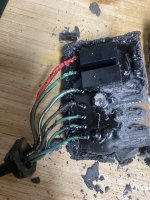
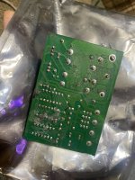
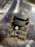
After I removed the hazard unit control box, I opened it up to see if I could find the source of the problem but the electronic board was potted with a black epoxy substance so things weren’t looking so great. Undeterred, I got out my heatgun and started heating up the epoxy, and I found that after heating up a section of the epoxy, I could chip off the potting material using a bamboo skewer stick.
I managed to get all the epoxy off but around that time I thought I was just wasting my time trying to repair the box so I came up with a different fix.
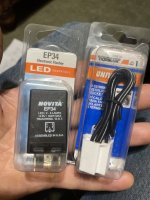
I went to the auto parts store and picked up an electronic flasher unit made by Novita. It was part number EP 34 ($15) and has three terminals. two of the terminals are power and ground and the third terminal goes to the flasher switch.
The original circuit works by sending a ground signal from the turn signal switch or hazard switch to the hazard unit, and the hazard unit sends a periodic 12v signal to the turn signal/hazard lights in the back.
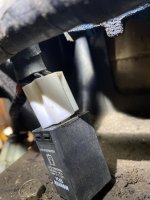
To modify the circuit, I cut the connector off of the hazard unit box and reused it. The red wire was 12 V power and I connected that to power the Novita flasher unit by connecting it to the +12 V input to the EP 34 flasher unit . The black wire was a ground signal so I connected that to the ground connection on the flasher unit and then I took the output from the flasher unit and connected it to the black wire going into the turn signal switch. since the original circuit connected that black wire on the turn signal switch to ground, You have to break that connection and I did that by removing the terminal from the turn signal, switch at the turn signal connector and spliced that wire into the output from the flasher unit.
The original hazard unit box has inputs for the left flasher, the right flasher and for the hazard switch. And it also has an output for the left turn signal and the right turn signal. All you need to do is just connect the left turn signal input to the left turn signal output wire on the reused connector from the hazard unit box that you cut off. Also, connect the right turn signal input wire to the right turn signal output wire.
Disconnect and remove the original flasher switch and replace it with a two pole single throw toggle switch that has 4 terminals on it. 2 of the poles on the switch are connected to output wire from the flasher unit and the other sides of the switch are connected to the left and right turn signal wires on the reused connector. So with the switch in the off position, the turn signals work when you move the turn signal switch left or right because it will send a flashing 12 V through the turn signal switch back down through the wires to the lights in the back. When you put the toggle switch in the on position, you’re sending the flashing 12 V signal from the flasher unit to both turn signal in the back.
Voila! Fixed the turn signals and hazard lights for $15. And since she used the original power lead that went to the hazard unit box, your new modified circuit is still protected by the fuse in the original circuit. The only thing you have to remember is to get rid of the ground connection that originally went into the turn signal switch and the hazard switch or else you’ll cause a short circuit
I included my messy mocked up schematic below
Searched online for schematic and found something close enough. The turn signal and hazard lights use a electronic control box called a hazard unit but is no longer available. They also wanted close to $500 when it was available so it wasn’t really a option.
After I removed the hazard unit control box, I opened it up to see if I could find the source of the problem but the electronic board was potted with a black epoxy substance so things weren’t looking so great. Undeterred, I got out my heatgun and started heating up the epoxy, and I found that after heating up a section of the epoxy, I could chip off the potting material using a bamboo skewer stick.
I managed to get all the epoxy off but around that time I thought I was just wasting my time trying to repair the box so I came up with a different fix.
I went to the auto parts store and picked up an electronic flasher unit made by Novita. It was part number EP 34 ($15) and has three terminals. two of the terminals are power and ground and the third terminal goes to the flasher switch.
The original circuit works by sending a ground signal from the turn signal switch or hazard switch to the hazard unit, and the hazard unit sends a periodic 12v signal to the turn signal/hazard lights in the back.
To modify the circuit, I cut the connector off of the hazard unit box and reused it. The red wire was 12 V power and I connected that to power the Novita flasher unit by connecting it to the +12 V input to the EP 34 flasher unit . The black wire was a ground signal so I connected that to the ground connection on the flasher unit and then I took the output from the flasher unit and connected it to the black wire going into the turn signal switch. since the original circuit connected that black wire on the turn signal switch to ground, You have to break that connection and I did that by removing the terminal from the turn signal, switch at the turn signal connector and spliced that wire into the output from the flasher unit.
The original hazard unit box has inputs for the left flasher, the right flasher and for the hazard switch. And it also has an output for the left turn signal and the right turn signal. All you need to do is just connect the left turn signal input to the left turn signal output wire on the reused connector from the hazard unit box that you cut off. Also, connect the right turn signal input wire to the right turn signal output wire.
Disconnect and remove the original flasher switch and replace it with a two pole single throw toggle switch that has 4 terminals on it. 2 of the poles on the switch are connected to output wire from the flasher unit and the other sides of the switch are connected to the left and right turn signal wires on the reused connector. So with the switch in the off position, the turn signals work when you move the turn signal switch left or right because it will send a flashing 12 V through the turn signal switch back down through the wires to the lights in the back. When you put the toggle switch in the on position, you’re sending the flashing 12 V signal from the flasher unit to both turn signal in the back.
Voila! Fixed the turn signals and hazard lights for $15. And since she used the original power lead that went to the hazard unit box, your new modified circuit is still protected by the fuse in the original circuit. The only thing you have to remember is to get rid of the ground connection that originally went into the turn signal switch and the hazard switch or else you’ll cause a short circuit
I included my messy mocked up schematic below
Attachments
Last edited: