Kubota mixup ?? on Pump Line hose and Power Beyond Line hose installation to loader

   / Kubota mixup ?? on Pump Line hose and Power Beyond Line hose installation to loader #1  

W5FL

Veteran Member
Joined
Apr 7, 2000
Messages
1,558
Location
Central Texas
Tractor
TYM T-1104/TX10 Loader Kubota M6800SD/LA1002 Loader Kubota RTV900
The dealer installed the loader a long time ago and it has always worked well, but when I was replacing all the loader hoses, I noticed that the diagrams in the LA1002 loader operators manual for the installation is different than the way my Kubota was delivered to me when new. First I connected the hoses up according to the manual, but the loader didn't work properly (wouldn't raise and actually went down). I had taken pictures and marked the cables, so I reversed the Pump line hose and the Power beyond line hose at the loader control as it was before removing the hoses, and that made it work ok! The Return line hose was never in question. Would anyone take a guess what reversing the hoses should have done? Should I put them back again or is it possible that the manual is wrong?

I also rigged up a gauge and measured the hydraulic pressure at the rear Auxiliary hydraulic connectors and the pressure looked ok, although a little low, but the rpm was also low. I was going to check the pressure at the loader, which comes from the Auxiliary block, but would you believe the quick connects are a different size (.75 diameter on the male) than the rear aux (.82 on the male which is standard for most implements). The Pressure Relief Valve works when a limit is hit for the aux and loader.

The loader, aux connector, and 3 point seems to work fine now, but sure like to know if I need to do anything else before it goes back in use running at PTO speed all day?


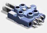
The connections are easy to differentiate as one has a 90 degree elbow (the Pump Line Hose) is the one nearest the front of the tractor and the other has a 45 degree elbow (the Pump Line Hose) is nearest the back end of the tractor.
Loader hydraulics Information 2.jpeg

The connections are also easy to see at the loader, as the return is a 1/2 inch hydraulic hose and the other two are 3/8 inch hydraulic hoses.
Loader hydraulics Information 4.jpeg

Return hose was ok.
Loader hydraulics Information 7.jpeg
 
   / Kubota mixup ?? on Pump Line hose and Power Beyond Line hose installation to loader #2  
I'd say you've definitely got it right now. Having them swapped would result in just the behavior you describe as the pump pressure would not be going to the loader cylinders when the valve is operated. Sounds like between the manual and the labeling of the hoses (and valve perhaps) that they are just easy to cross.
 
   / Kubota mixup ?? on Pump Line hose and Power Beyond Line hose installation to loader #3  
Sounds as it is correct as previous post said but be careful anytime swapping hoses If you were to dead head pump with no relief serious damage will occur. good luck
 
   / Kubota mixup ?? on Pump Line hose and Power Beyond Line hose installation to loader #4  
It would not be the first manual to have not kept pace with engineering or production changes.
Dave M7040
 
   / Kubota mixup ?? on Pump Line hose and Power Beyond Line hose installation to loader #5  
Not surprised there would be an error in the instructions....
 
   / Kubota mixup ?? on Pump Line hose and Power Beyond Line hose installation to loader #6  
Can you ID the IN port and relief valve on the FEL valve?

The IN hose is usually located very close to the relief valve.
 
   / Kubota mixup ?? on Pump Line hose and Power Beyond Line hose installation to loader
  • Thread Starter
#7  
Thanks for all the responses so far! I have a workshop manual for the tractor, but not for the loader (just the operator's manual).

The hoses were not labeled (unless the yellow paint was the label).

The FEL valve is shown in the photo below. It is a HUSCO and in the picture it looks like it is missing some kind of cover where you can see the oily pipe with a gasket showing.

JJ, here is a photo of the valve (taken from the loader side) and you can see the RETURN line next to the valve, and the next hose over (towards the tractor) goes to the right angle connection (labeled with a red band originally) closest to the front of the tractor . Is this what you are calling the IN port? I am not familiar with what is the power beyond on this loader valve. Is the hose coming out of the valve on the side facing the rear of the tractor the POWER input or the POWER BEYOND port?

Out of curiosity, why are there both a POWER and a POWER BEYOND on a loader valve?

Loader Control Valve DSC_6757.jpg
 
   / Kubota mixup ?? on Pump Line hose and Power Beyond Line hose installation to loader #8  
I can't see your valve clearly.

If your loader has a PB port and it probably does, you should have 7 hoses connected.

IN port from pump/hyd blk

return/tank port

PB port with adapter.

4 work ports.

Your pump probably feeds the hyd block, so your flow path might look like this.

Pump, hyd blk, FEL, PB, back to hyd blk , 3pt, tank.

Cyl expended fluid goes to the tank /return port.

If you have a remote valve, it will be before the 3pt.

I believe your valve is a 9210, and if so, the rounded hex nut on the top of the valve is the relief valve.

On the bottom of the valve inline with the relief valve is the IN port. Optional port is on the face of the valve under the relief port.

The other bottom port is the Tank port.

PB port is on the face of the valve to the left looking at the ports of the valve.

Your lift spool is by the relief valve.

You may have regen. You will have to check the action to see if you have two dump speeds..
 
   / Kubota mixup ?? on Pump Line hose and Power Beyond Line hose installation to loader
  • Thread Starter
#10  
Went back and cleaned off the ID plate and made another photo of the way the lines are connected now. You can see the 4 lines at the top going to the loader cylinders, the line closest to the valve goes to the return line (it is the only 1/2 inch line).

The one with the red tape I put on the new line goes to the right angle connector shown in the third picture with the wrench on it and the remote lever next to it. Does this look like the power beyond line or the pump line?

There are six lines on this surface.

You can see the PRV in the second photo also. Total of seven lines go to the valve. You can read the ID plate in this picture, but not sure which one is the model number.

The line that also shows is coming from the driver side of the valve (on a surface by itself) and also shows in the second photo as the line on the left side of the picture "may be" the power beyond line?

Loader DSC_6873 - Version 2.jpg


Loader PRV DSC_6832.jpg


Red Marked Line DSC_6791.jpg
 
Last edited:

Tractor & Equipment Auctions

2011 KOMATSU PC160LC-8 (A52472)
2011 KOMATSU...
1271 (A50490)
1271 (A50490)
Deere 325G (A50120)
Deere 325G (A50120)
(4) Radial ST 225/75 R15 Tires (A50121)
(4) Radial ST...
2015 John Deere 410E 40 Ton Articulated Off-Road T/A Dump Truck (A50322)
2015 John Deere...
2022 New Holland Workmaster 120 MFWD Compact Utility Tractor (A52748)
2022 New Holland...
 
Top