mclarenaml
New member
Following my earlier note regarding play (a lot!) in the rear splined section of the driveshaft, I've bitten the bullet and gone ahead and extended the shaft by 18mm. The rear yoke is now fully engaged on the input shaft of the transaxle - in fact, the shaft extends into the yoke itself by about 2mm. It's rock solid - from the 2mm you could move the rear yoke side to side previously, it's now 0.
Here's a bit of a precis and photos of what we have done.
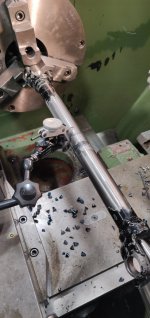
First off, once the driveshaft was out and the universal's removed, we drilled centres into each end of the shaft itself. This was to give us a basis for verifying alignment later. Strangely, while one centre looked dead in the middle of the yoke opening, the other looked about a mm out. We checked this multiple times, and the centre was definitely concentric with the shaft, so suspicious that the yoke was not welded on 100% true. That wouldn't help, but not much we could do about this.
Also before parting the shaft, scribed two reference lines outside the area we were going to work on, and took a measurement between these. Once we had cut the shaft (parted in a lathe) and cleaned up the two ends, the target was this measurement plus 18mm when finished. We also scribed a longitudinal line so the two halves would be in the same alignment as previously - not sure how important this is.
Now the point of no return, the shaft was split in two, the ends cleaned up, and counterbored to give us a 10mm socket to align the extension. The ends were vee'd to provide access for the welder.
An extension 'bobbin' was machined from mild steel (same as the shaft) to give a final extension of the 18mm required. This has 10mm spigots at each end to locate in the halves of the shaft, and was also vee'd for welder access.
This was set up on v blocks. The initial welds were tigged to ensure we welded right into the root of the join. Once joined, and alignment verified, the rest of the weld was completed with a MIG. Tig would have been too slow!
Once cooled and cleaned up, the longer shaft was mounted between centres in the lathe, and the alignment verified. It was around 0.5mm out, so this was corrected in a press. We ended up with 0.15mm runout, which we were happy with.
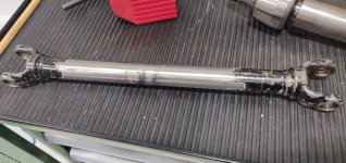
It's all been repainted and reassembled. It was close as expected, but went together without any drama. The rear fitting is now silky smooth, with no movement at all - you can hold this when it's running. There is a little bit of vibration at the front of the shaft, but I'm suspicious this is the off centre yoke we noticed earlier. Definitely there is no perceptible movement at either end when nothing is running. But it's minor compared to what we started with!
Now some gotchas to be careful of if you attempt the same thing!
First, check exactly how much extension you need. I suspect tractors are not identical - for instance, many people can remove the standard shaft without dismantling universal's. With mine, it's close, but no way, and I always needed to disassemble/reassembled the rear universal in situ. What you are aiming for is for the rear yoke to fully engage in the transaxle splines.
Next verify that you will be able to assemble the rear universal when the shaft is this much longer - it definitely won't install complete. I found the easiest was able to simulate this by using the fan mounting boss - locate this out on the shaft by the extension length, and give it a go!
In my case, I also removed around 4mm from the fan boss, and also machined the centre of the fan out to allow the rear yoke to slide back inside. This have me another 4mm to play with when assembling.
It was quite a bit of work, but sooo much better. In fact, of I ever needed to replace the shaft, I'd do this again before installing it. It really is a poor design, but this lets it work without flogging itself to death.
Andrew
Here's a bit of a precis and photos of what we have done.
First off, once the driveshaft was out and the universal's removed, we drilled centres into each end of the shaft itself. This was to give us a basis for verifying alignment later. Strangely, while one centre looked dead in the middle of the yoke opening, the other looked about a mm out. We checked this multiple times, and the centre was definitely concentric with the shaft, so suspicious that the yoke was not welded on 100% true. That wouldn't help, but not much we could do about this.
Also before parting the shaft, scribed two reference lines outside the area we were going to work on, and took a measurement between these. Once we had cut the shaft (parted in a lathe) and cleaned up the two ends, the target was this measurement plus 18mm when finished. We also scribed a longitudinal line so the two halves would be in the same alignment as previously - not sure how important this is.
Now the point of no return, the shaft was split in two, the ends cleaned up, and counterbored to give us a 10mm socket to align the extension. The ends were vee'd to provide access for the welder.
An extension 'bobbin' was machined from mild steel (same as the shaft) to give a final extension of the 18mm required. This has 10mm spigots at each end to locate in the halves of the shaft, and was also vee'd for welder access.
This was set up on v blocks. The initial welds were tigged to ensure we welded right into the root of the join. Once joined, and alignment verified, the rest of the weld was completed with a MIG. Tig would have been too slow!
Once cooled and cleaned up, the longer shaft was mounted between centres in the lathe, and the alignment verified. It was around 0.5mm out, so this was corrected in a press. We ended up with 0.15mm runout, which we were happy with.
It's all been repainted and reassembled. It was close as expected, but went together without any drama. The rear fitting is now silky smooth, with no movement at all - you can hold this when it's running. There is a little bit of vibration at the front of the shaft, but I'm suspicious this is the off centre yoke we noticed earlier. Definitely there is no perceptible movement at either end when nothing is running. But it's minor compared to what we started with!
Now some gotchas to be careful of if you attempt the same thing!
First, check exactly how much extension you need. I suspect tractors are not identical - for instance, many people can remove the standard shaft without dismantling universal's. With mine, it's close, but no way, and I always needed to disassemble/reassembled the rear universal in situ. What you are aiming for is for the rear yoke to fully engage in the transaxle splines.
Next verify that you will be able to assemble the rear universal when the shaft is this much longer - it definitely won't install complete. I found the easiest was able to simulate this by using the fan mounting boss - locate this out on the shaft by the extension length, and give it a go!
In my case, I also removed around 4mm from the fan boss, and also machined the centre of the fan out to allow the rear yoke to slide back inside. This have me another 4mm to play with when assembling.
It was quite a bit of work, but sooo much better. In fact, of I ever needed to replace the shaft, I'd do this again before installing it. It really is a poor design, but this lets it work without flogging itself to death.
Andrew
Attachments
-
 IMG_20230624_121545.jpg1.3 MB · Views: 129
 -
 IMG_20230704_132902.jpg997.9 KB · Views: 124
 -
 IMG_20230624_133404.jpg1,006.1 KB · Views: 139
 -
 IMG_20230624_155958.jpg1 MB · Views: 277
 -
 IMG_20230624_133019.jpg1.2 MB · Views: 140
 -
 IMG_20230624_140421.jpg1.2 MB · Views: 139
 -
 IMG_20230624_155716.jpg1.3 MB · Views: 134
")