How rigid is a 1" x 4" flat bar ?

   / How rigid is a 1" x 4" flat bar ? #31  
I thought of that. They actually said I could go up to 3" wide on the tab but the annular cutters I have only got to 1" depth of cut hence the 1" thick I had in mind. I guess I could go thicker but I would need to buy another annular cutter.

I was thinking of setting the straps in the concrete and leaving them tall. Once set I was going to use a rotary laser and mark a level spot on them and then drill the 1" holes for the bolts with my mag drill and then cut off the tops and round the corners.

You certainly have a cool project going. The wider apart the better on the shore anchors. Should be a great party dock.
 
   / How rigid is a 1" x 4" flat bar ? #32  
Once set I was going to use a rotary laser and mark a level spot on them and then drill the 1" holes for the bolts with my mag drill and.....

That will work, if your water is level :laughing:
For sure, your 1 x 4 will be more than adequate.
 
   / How rigid is a 1" x 4" flat bar ? #33  
Yes. See the attachment in the circle in this picture.

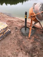
Instead of bolting it to the side of a concrete pillar or setting a heavy pipe or square tube and welding the mounting tab on to it I was thinking of having the concrete underground and having a 1" x 4" flat strap extending up vertically 12" from he ground and drilling a 1" hole in it for the mount. Basically imagine this picture without the concrete and the mounting tab just sticking up out of the ground.
011.JPG


Since there are two, one on each side of the ramp, 1" x 4" strap should work just fine.

I build things using the TLAR School of Engineering method. (That Looks About Right). :D
 
   / How rigid is a 1" x 4" flat bar ? #34  
Pair two pieces up side by side after you drill the holes, weld them together down the middle. You'll be fine then.
 
   / How rigid is a 1" x 4" flat bar ?
  • Thread Starter
#35  
Pair two pieces up side by side after you drill the holes, weld them together down the middle. You'll be fine then.

While a good idea and a trick I have used in the past it won't work easily for this. In order to have the holes at the same elevation I plan to set the bars in the concrete first, let it set overnight and then come back and mark the heights and drill the holes with a mag drill. Two 1"x4" bars sandwiched together would weigh over 160lbs. Would be tough to position those in the exact horizontal and vertical position simultaneously and put the concrete around them.
 
   / How rigid is a 1" x 4" flat bar ? #36  
Disclaimer......whatever advice contained within this post is worth exactly what you pay for it. And in the event of a failure, or error on my part, you are entitled to a full refund of what you pay me for this advise.

Now that thats out of the way.....I cannot say weather the 1x4 bar is gonna work or not. Because its not a simple problem. Soil, concrete, footing size, etc. The steel may rip right out of the concrete, or the concrete may rip out of the ground, or the steel may break/bend.....I dont know the loads involved.....and dont know what the MFG has designed their piers of I-beams to be able to withstand. And the ones you pictured.....dont even know what size beams those are.

But what we can do is make some comparisons.

With such short beams.....even the 4-foot I-beams.....deflection is really not a concern. Rather stress. If you are using A36 (36ksi steel), and you exceed stress levels of 36ksi.....that dont mean its going to break. It means its deflected far enough that it will no longer return to shape. (It bent:laughing:)

So, sparing everyone the long math and formulas....

A 1x4 piece of flat bar, in the strong 4" direction....That can handle ~8000# before exceeding 36,000psi
Same bar, in the weaker 1" direction.....That can handle ~2000# before exceeding 36,000psi


Assuming the pictures of the dock in your first post are 48" tall piers.....

The closest two beams in strength are a W6x16 being slightly weaker, and a W6x20 being slightly stronger.

A W6x16 sticking up 48" would handle 7650# in the X direction and 1650# in the Y
A W6x20 sticking up 48: would handle 10,000# in the X and 3300# in the Y direction.

W6x16 is a 6" x 4" I beam
W6x20 is a 6" x 6" I beam.

And based on the design of those stabilizers......if their intent is to triangulate so the dock cannot sway in the wind.....it looks like 99% of your force is going to be in the strong direction. Dont really see how its possible to get much side loading on that 1x4 bar unless you run into it with a tractor:laughing:


If you want to know how a different shape (beam, tube, etc) stack up in comparison, let me know. Punching the numbers in a calc are pretty easy. As long as they are a standard shape and I can source specs for said shape. Weldments or odd/modified shapes are a little more challenging.
 
   / How rigid is a 1" x 4" flat bar ? #37  
Subscribed. I'm planning a re-do to 'floating', as ground water (pond level) fluctuates >3' according to 'macro' climate variations. I've had ice lock around embedded dock posts. When a big spring rain/melt floats 4" of ice higher, what's attached goes up with it. My swing arm(s) and gangway will be wood and maybe 12' long, max. Wish me luck trying upper and lower arms to control tipping of a 4' x 12' 'T' at the end. :rolleyes: ... :laughing:

Having 'bars' on both sides of the OP's gangway would change the dynamic of side loading but it's still there, so I'm also concerned about that effect in strong winds. As for the twisting of any vertical bar: 'short' concentrates the force over a smaller area, thus it's easier to deform vs flex. Allen wrench comparison: more breakout force delivered with long end in socket and snipe vs twisting the small end into a spiral by concentrating force into the 'short leg'.

'Galvanic' corrosion isn't the only risk if you think long term-enough with metals .. and 'mixing' them. Paint on metal can peel and rust from the edges to underneath, so you'd want to keep an eye on whatever weatherproofing. Adding to what marchanna said, bushed pivots can also be refitted for wear over time, another thing to watch, but that doesn't automatically add up to work unless needed.
 
   / How rigid is a 1" x 4" flat bar ?
  • Thread Starter
#38  
Thanks for the replies and calculations.

A bit of an update. I measured and marked the hole locations yesterday. I also measured my 1" annular cutter that has a reported 1" depth of cut. It will actually cut 1.5" deep. I picked up some 1.5" x 4" flat bar today. They would not sell me less than a 20' stick so I got that. Instead of wasting it I figured why not go deeper on the holes. It only amounts to more concrete. So tomorrow I will drill the two 18" diameter holes 8' deep and set the 1.5" x 4" bar in them. Will be 1,680 lbs of concrete per hole.

After seeing where the holes are I think the holes for the stiff arms will only be like 8-10" above the concrete not a 12" so with the shorter length and the 1.5" x 4" bar instead of 1" x 4" bar I think it will be fine.

I will try and get some pictures as we progress.
 
   / How rigid is a 1" x 4" flat bar ?
  • Thread Starter
#39  
Well I made some progress today.

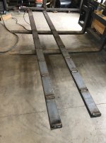
I started with two pieces of 1.5" x. 4" flat bar 10' long.

It wouldn't fit in the welding forum if there wasn't a little welding. I welded pieces of rebar on to the flat bar every 12" on both sides, staggered 6" on the front and back. I did this so the concrete could hold the bar in place and there was no chance of it pulling out of the concrete. I have pulled pipe fence posts before that were set in concrete and had the concrete stay and the pipe pull out

rebar.JPG


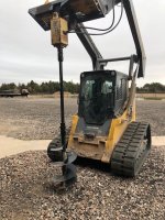
Next I got this ready to go to drill to the depth needed. That is an 18" auger and 8' from the tip to the gear box.

skidsteer.JPG


Then I drilled the hole. It is DEEP. I wouldn't want to fall in there though I am likely too fat to go very far.

hole.JPG

IMG_5210.JPG


And last here is the bar set in place with 22 80 lb bags of quickcrete. The chain welded on top is what we used to lift it with the skid steer and lower it into the hole. Each bar weighed over 200 lbs. Tomorrow after the concrete is set I am going to drill the 1" holes in the bars approx 8-10" from ground level and cut off and round the tops.

filled.JPG
 
   / How rigid is a 1" x 4" flat bar ? #40  
Here is a better pic of what the finished product will be like. This one was actually done incorrectly with the mounts too close to the ground as the pond went down and now the stiff arms are contacting ground.

Lateral load is my concern. I doubt the 1x4 bar will bend in the 4" direction. It will definitely be weaker in the 1" direction but still I wonder how strong can those aluminum brackets in my original pictures be? They look to be two pieces of angle welded together and maybe 3/8" each for a total of 3/4". Would a a 1" x 4" flat steel bar only sticking out 12" bend before that aluminum bracket would?

Definitely not wanting to cheap out. Price is of little concern on these anchors. the dock is expensive and I want it staying put. My main goal other than it staying put is have the least obtrusive design possible without something sticking up our out for kids playing around there to run into.

The dock is 15 x30, and the upper deck is 12x15. Yes it will extend out perpendicular from the shore. The gangway is 30' long.

Attached is a picture that is similar to what it will look like when finished.
Loading will never be truly lateral. Side loads on the dock will resolve into tension and compression in the arms that locate the dock. Since the arms are relatively close together in comparison to the standoff of the dock the alternate push/pull forces applied to your mooring will be pretty big.
The orig I beam attachment @ 4' up would allow some significant "spring" in the beams as they took their loads.​
You drastically limit that spring attaching lower - but not to worry. - The arms themselves are springs of a sort, compressing and extending elastically.

I think your idea is fine but you must allow for fatigue of the mooring tabs at the transition into concrete. -- Use 1 X 6". - Exit the concrete with the full 6" to a height of about 1" and taper the front and back sides equally from that point to achieve 4" width at the attach point. Before placing this shape in concrete radius the corners of the rectangular shape from about 1" below concrete grade all the way to the top. The corners are where a crack would occur, if ever.​
A flap disc wheel will allow you to accomplish this well iteratively in a controlled and forgiving fashion. Any rounded break of the abrupt edges is improvement. A sizable radius, ~1/4", is better. No magic there. Just eyeball it.
 

Tractor & Equipment Auctions

2012 PETERBILT 367 FLATTOP SLEEPER (A45333)
2012 PETERBILT 367...
Deere 50G (A44501)
Deere 50G (A44501)
MISC PALLET OF VALVES AND HOSES (A45046)
MISC PALLET OF...
2017 JLG SkyTrak 10054 10,000LB 4x4 Rough Terrain Telehandler (A42742)
2017 JLG SkyTrak...
White Planter Parts (A39855)
White Planter...
2003 Dodge Ram 1500 Front Bumper | OEM Replacement | Durable and Ready to Install (A44789)
2003 Dodge Ram...
 
Top