Help with cantilever beam stress

/ Help with cantilever beam stress #1  

CraigM

Silver Member
Joined
May 3, 2000
Messages
115
Location
Golden, IL
Tractor
B2150HSD, JD3020
I'm designing a hay fork for my B2150. It will lift 4 bales at a time. The bales are stacked 2 wide x 2 high to make a 200 pound cube about 36 on a side. I envision 4-8 round spikes, like a tine bucket

A quick test of a possible spike using a 50# bag of feed in a 5 gallon bucket says that 5/8" diameter rod clamped in a pipe vice will hold 53# at a distance of 30" from the support, and spring back when the weight is removed.

With that as a starting point, I got out the books to 'experiment' with different rod diameters and lengths. When I calculated the stress in the 5/8" test, I got 66ksi. Interesting for mild steel that should only be able to withstand 30-36ksi. I went back to the shop and tried again with other rods and was able to get calculated stresses as high as 100ksi without bending the rods.

The equations I'm using are:
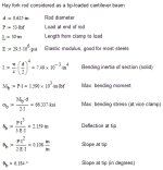
Stress in a cantilever beam = (My)/I. M is bending moment, y is distance from neutral axis...the radius of the rod in this case, and I is (Pi/4)r^4 where r is the radius of the rod. Pi is that magic 3.14 but I'll have to write it as Pi since I don't know how to make the symbol.

When I do the calculations with 5/8" dia, 53#, and 30" I get M = 1590 in#, I = .0075 in^4, y=.3125 in. This gives a stress of 66ksi.

It's been way too long since school and engineering lab. Can someone tell me what I'm missing?
 
/ Help with cantilever beam stress #2  
Your math all sounds right, I got the same answer. Google for "Beamboy". nice freeware beam stress program, even has some channels, I-beams, etc preloaded in there for I, etc.
 
Last edited:
/ Help with cantilever beam stress #3  
Did you check with a straightedge or something to see if the bar sprung all the way back? Could be that it took a very slight set that was hard to notice.

Also, what grade is the steel you have, and is it hot rolled or cold rolled? Cold rolled bars have higher strength than their hot rolled siblings due to work hardening during the cold rolling process. Might account for the difference, but not up to 100ksi, that's getting up in the heat treated alloy steel range there!
 
/ Help with cantilever beam stress #4  
Here's what we got:

5/8" Diameter Rod - S (section modulus) = .0239685 in3

Momemt = 1.590 in-kips

fb= M/S
fb= 66.33 ksi

To still be in the elastic range on the stress/strain curve, your steel would have a tensile strength of 100ksi. Possible, depending on the grade of steel, especially in rounds. Round bars come in tensile stregths well over 150ksi.

Where did you get the stuff?
 
/ Help with cantilever beam stress #5  
Like a starved Chihuahua on a pork chop, I can't stay away from this one, mainly because it gives me an excuse to use Mathcad! :eek: (hopeless geek engineer). I checked the math as well (it's spot on), and went on to calculate the deflection and slope at the end, which should be nearly 2-3/16" and 6.2ー (or .108 in/in) at the bucket handle. That's pretty noticeable, did you see anything like that? It seems to me that if you had the rod clamped horizontally in a vice, the bucket would want to slide off the end.

I'm not doubting your word - your tech skills are obviously strong enough. Actually, your attitude seems like mine - you want the numbers to reflect reality.

So like Michigan Iron says, you must have some mighty good stuff there, maybe heat treated 4140 or something. Unless, like Huskerboy says, it took a set and you just couldn't tell (easily).

Curiously yours,

Tom
(calc's attached as graphic)
 

Attachments

  • Hay_fork_rod_calc.jpg
    Hay_fork_rod_calc.jpg
    78.1 KB · Views: 4,696
/ Help with cantilever beam stress #6  
Now add in the bending forces when you run it into the ground.:D
 
/ Help with cantilever beam stress #7  
What kind of feed was it? I just measured a 50# bag of sweet feed and it was roughly 26" x 16" x 4.25" = 1768in^3 = 7.65gal

It would never fit in a 5 gal bucket. :)


Mild steel can have a pretty wide range for yield strength.
McMaster-Carr
 
/ Help with cantilever beam stress
  • Thread Starter
#8  
We all get the same textbook stress, but it still doesn't add up. I repeated the experiment today, but measured the deflection of the rod at the bucket. Actually 1/4" from the bucket, but that should be close enough. The rod deflected 13/16" (.813) and sprung back exactly to the starting point, as best as I could measure. Tom, I didn't calculate the deflection, but your equation is the same one I would use, so we should get the same answer. Naturally, the experiment and the math don't agree.

Michigan and Husker, the steel came from the hot roll rack at the local supplier. They also sell A36 steel, which yields at 36ksi, and stressproof steel, which I believe is equivalent to 1040/1045. That has a yield of 42-45ksi. If one of these had found its way into the rack, it still should have bent as the calculated stress was almost 1.5x the yield. The ends are mushroomed a bit from using it as a long punch to drive a stuck shaft out of the tractor, so I doubt it's anything special or heat treated. And remember the other tests Iv'e done that calculate out to a little over 100ksi, but the rod didn't bend. That was a 1/2" rod that I'm sure is nothing special.

Brad, actually it was oyster shell for the hens. Sort of a feed. I figured that calling it feed would save questions about oyster shells. That page from McMaster is very interesting. I had no idea that you could get mild steel to that kind of strength. I assume that's by heat treatment. It still doesn't answer the problem entirely since heat treatable steel normally comes from the supplier in a soft state. And it wouldn't explain why I get less than half the deflection that the math predicts. Still, it is a great suggestion. I will call the steel place tomorrow and get some numbers.

So, we all get the same calculated stress, which is good news. My brain hasn't entirely turned to rust. But we can't explain the differences between the theory and reality. That part makes me nervous, especially with something so apparently simple. I don't believe that we are all doing the wrong calculations, so the only answer is that the steel is something fancy, but I doubt that too. This is going to bug me until I figure it out. As Tom said 'hopeless geek engineer'.

Thanks Everyone
 
/ Help with cantilever beam stress #9  
Here is the answer, mostly, to your question...

If you buy 'regular old' 36ksi structural steel keep in mind that the 36 ksi is the minimum yield strength. Making steel is an art, more than a science and making a batch that doesn't meet the strength requirements is expensive.

It is a lot easier and more cost effective to make a batch of steel that will exceed the requirements.
Years ago we were tearing up an implement on a potato farm, I can't even remember what it was. Calculations showed that a 5/8 -inch grade 5 bolt would fail and protect the implement. We ended up with 'no grade' 1/4-20 bolts with the threads in the shear plane, by experiment...

Now, you may have a different grade of steel than A36 but expect it to have a higher strength than 'advertised' as well.
 
/ Help with cantilever beam stress #10  
Good point and true, henerythe8th, but what is bothering me (and Craig, at least) is the fact that the deflections aren't anywhere near where they should be, and that is based on an entirely linear calculation (no "yield" or permanent bending).

With Craig holding his bar in a vice, it's hard to believe he'd measure less deflection than a built-in cantilever calculation, which of course assumes an infinitely stiff "wall" that the beam is attached to. That's difficult to duplicate in real life.

So, yeah, you can heat-treat plain ol' steel up to some pretty good yields, but for steel the elastic modulus is well established, so the deflections shouldn't be that far off, much less in the "too low" direction.

Are we to the point that "this thread is worthless without pics?" ;) This starved Chihuahua is still perplexed. Is gravity not working too well out your way, Craig? :D Are you able to get the OD accurately (i.e not eyeballing from a tape measure)? I've missed diameters significantly that way, and this case is pretty sensitive to it - a 3/4" rod calc's at only 1.04" deflection and to match your .813 would probably be a 20mm rod (I hate metric). Just for giggles, wrap a piece of duct tape or paper around it, cut it with a razor at the meeting, unwrap it, measure and divide by pi. Unless, of course, you have calipers or a micrometer handy. & unless you are alrady sure of the OD, then we're back in the Twilight Zone.

Tom
 
Last edited:
/ Help with cantilever beam stress
  • Thread Starter
#11  
Tom:

Here are some pictures of the experiment.

I repeated the experiment with different setup that allowed me to measure very accurately. Caliper says that rod is .627. Interesting that the end that the bucket hangs on measures about .635 for the first half inch or so. Mushroomed from the previously mentioned use of that rod as a punch. I tried to take pictures of the caliper readings, but couldn't convince the camera to focus on the caliper. I used the caliper depth gage to measure from the top of the bar to the top of the rod. By keeping the depth rod on the caliper against the end of the bar, I got a very repeatable setup. The measurement was about .25 behind the bucket handle.

When I first set it up, the bar was lying flat, and the weight of my hand deflected it when I tried to measure. The first readings were deflection of .761, and return of only .744. This may have been due to my hand deflecting the bar, or it might have yielded. Could lso have been the rod settling into a position. The clamp on the angle is far from ideal. It took very little force to spring the bar measureably. I put the bar up on edge as in the picture and was able to repeatedly load and unload the rod. The deflection was .759 each time, and each time it came back to the starting measurement. I did not reposition the rod at any time. What happened to 7/8 deflection? Good question. Last time I measured it with a tape measure marked in 32nds. Seemed like I was getting good measurements, but maybe not. Still, 1/8" seems a lot of difference.

If the rod yielded at a calculated stress of 66ksi, I'd expect something that left no doubt. Is it yielding slightly and workhardening? The rod checks as straight as it ever did. It has a few slight wiggles, but always did.

The clamping setup is as close to cantilever as I can get. I was trying to remember shear/moment diagrams because I guess the setup could also be considered simply suported at the clamp with a balancing force at the end inside the square tube. If I remember it right, the shear/moment diagram would be the same as far as the cantilevered end goes, and would not change the analysis.
 
/ Help with cantilever beam stress #12  
I worried about this same thing many years ago, and came to the conclusion that we are using the wrong neutral axis; put differently, we assume that the neutral axis is at the center of the cross section and therefore that the distance from the neutral axis to the extreme fiber is 1/2 the diameter for a round, and 1/2 the height for a square or rectangle. But the "real" neutral axis is not in the center; it is actually located a very small distance from the bottom surface.

See the attached sketch. The top example is the typical textbook formula for section modulus that assumes that the neutral axis is in the center. But the neutral axis is defined as the point where the fibers are in neither compression nor tension. This first example assumes that when the bar bends, all the fibers above the centerline are in tension and the fibers below the centerline are in compression. If that is true, then the neutral axis is through the center and the formula gives the correct stress for the extreme fiber.

But metal does not deform like example one assumes. If it did, the bottom surface of the beam would compress exactly the same amount that the top surface stretched; otherwise, the fibers in the center woud be stretched or compressed. Said another way, the example assumes that the two ends of the bar (that is, each side of the cross section) pivot around the center when it bends.

But experience teaches that metal does not bend like that, because it does not behave the same way in compression that it does in tension. Since metal is virtually incompressible, almost none of the fibers in the bar are in compression except those at the very bottom surface. All the other fibers are in tension. In effect, when it bends the two parts of the bar rotate (relative to each other) around the bottom surface (more precisely, a point just inside the bottom surface, since at least a few fibers on the lower surface must be in (very great) compression to maintain the bar in equilibrium).

Therefore, the neutral fibers, and therefore the neutral axis, are for all practical purposes on the inside surface of the bend. Thus the distance from the neutral axis to the extreme fiber is actually the height of the bar rather than one-half the height and the section modulus is thus doubled.

Since the stress is torque divided by section modulus, when the section modulus is doubled (ie, when the neutral axis is the bottom surface) the stress is halved. And naturally, the deflection is half or even less. Compare the two formulas on the attached sketch.

The enclosed example tries to demonstrate these concepts.

Thus when designing using the assumption that the neutral axis is in the center of a beam we are (perhaps unknowingly) adding a safetly factor of about two.

These concepts are clearest to me if I consider the wide flange (or "H") section (often mislabeled as an "I-beam"). Assume it is welded at one end to an immovable wall, and that we load the other end until it finally deforms and collapses. We know that it will break at the wall since the torque is greatest there. And we know from experience that when it deforms it will do so by elongating at the top flange and then down the web, and that neither the bottom half of the web nor the bottom flange will be compressed into a shorter space. That is because the neutral fibers are not in the middle of the web, but rather at the bottom outside surface of the bottom flange.

You get the same result if you consider suporting the section on a pivot in the center and loading each end equally until it breaks in the center.

Many reference books, such as Machinery's Handbook, give formulas for section modulus assuming the neutral axis is in the center (actually the center of gravity) and also assuming it is on one surface.

I typically use the formulas with the neutral axis on one surface and then incorporate a generous safety factor in the final sizing. It is easier for me to make all the calculations as accurately as I can and then apply the safety factor in one operation rather than to try to build in a small safety factor at each stage.
 

Attachments

  • section modulus.pdf
    29.6 KB · Views: 288
/ Help with cantilever beam stress
  • Thread Starter
#13  
Farmerford, I've never seen an I-beam fail, but I have bent steel from time to time. It does seem to bend like you describe, mostly stretching on top and not changing much over the anvil.

As far as applying that logic to designing a beam to make it strong enough, you are bucking at least 100 years of proven engineering experience. If I remember correctly, the neutral axis is the plane where the monent of inertia (I) of the material above is equal to the I of the material below. Said another way, there is as much strength above as below the neutral axis. For a round rod, that has to be the center.

The big thing with the equations in Machinerys and the like is that they only apply up until the material yields. After that, you are no longer looking at elastic deformation and all bets are off. Since the reason for doing all of this is to find out how much load a bale spike can carry before it yields, the equations should work. Granted, they don't seem to be working, but they use those equations to design airplane wings and bridges, so I must be missing something.

The classic example to demonstrate the tension and compresson in a material behaving elastically (not yielded yet) is the marked eraser. Take a big rubber eraser, Draw a line down the center (this is the neutral axis) and a bunch of crossing lines. When you flex the eraser, you can see the tension in the top by the crossing lines moving apart, and the compression below by them moving together. The continuous change from max tension on top to max compression on bottom sets up shear stresses through the material.
 
/ Help with cantilever beam stress #14  
Your ruler says L = 20". You had it at 30" in post #1. Looking at your c-clamp, the effective length is more like 21"

Using a modulus of 30,000,000psi which is independant of temper, I get a deflection of 0.73 - not too shabby.

I used D = 0.625. There is probably some mill scale on the rod.
 
/ Help with cantilever beam stress
  • Thread Starter
#15  
I can hardly see to type because of the bright red glow from my face. Guess I win bonehead of the week. Post #1 ended with 'can someone tell me what I'm missing? You did. I have 30 stuck in by brain as the first guess for length of the spikes on the fork.

I agree that the clamping setup probably increases the effective length of the experiment. Using the proper length in the calculations at least gets the experiment and the theory in the same ballpark. If we assume that the effective length is 21" as confirmed by your deflection calculation, that gives a stress of a bit over 46ksi. I still have a little trouble with that one, but given what I learned from your link to McMaster, and what Henrythe8th said about steel making and meeting minimum yield specs, it's possible.

I'm going to re-test the other pieces that gave me such high stress values. This setup isn't great as far as the clamp, but the old pipe vice was worse. It was just quicker than cobbling another rig together.
 
/ Help with cantilever beam stress #16  
The clamped end of the bar is not as precisely fixed as you might think it is. Even though you have it clamped so it can't deflect vertically, it can still move and thus stretch longitudinally. The additional length of the bar extending inside of the square tubing is distributing some of the stress as that steel is undoubtedly also stretching along the top cord. More of the length of the steel is stretching than your calculations are accounting for, so the amount of strain per unit area is less than you think. By crude estimation, you probably have an error factor of 1.6 up to a theoretical max of 2x due to ignoring the portion of the bar inside the square tubing.

You will get better results modeling it as a combination of a point load at the end, another point load at the clamp, and a tapering continuous load along the inside of the square tubing offsetting the other loads.

Think of the different result you would get if the rod was tightly fitted through a press fit hole in a 1" plate and plug welded (ignoring the heating issues) on the other side to completely immobilize it.

- Rick
 
/ Help with cantilever beam stress #17  
Ha ha we all make "dumb" mistakes. It's a good thing you posted such good pictures.

If you clamp the bar to the top of a flat surface so it comes off a good sharp edge I think you'll make a pretty good cantilever. Your tall c-clamp will work a little better too grabbing a thicker bite. Add another c-clamp further back to control the bar.

It's not all that magic. A center point support with a "balance beam" load on each end follows the same deflection path as a cantilever beam of half the length.

With a 50# share of the bales in a load distributed over 36", the rod you are testing seems just strong enough. The bales won't bend the rods but they probably will bend when you dig them into the ground or dump too close to the ground, a pile etc. I would use 1" square solid HRS for that application. If you have a supply of the 5/8" stock cheap/free you could weld 3 together in a triangle to make a robust spike. I'm sure you'll want to use it for moving brush, etc. so you might as well over-build it.

If you go with the 5/8", at least you'll be able to straighten them when they do bend, and they'll work harden to boot.

Brad
 
/ Help with cantilever beam stress #18  
Craig:

You win an offical "Tom award" (guess who it's named after). Kinda like when you go to measure "exactly" with a tape and you hold it on the 1" mark and then go back and forget to knock off the 1".

Looks like you got this one. Sorry I got back to the thread late, I've been out taking a half-dozen felled mulberries apart all weekend, and I'm just setting to to design my Carry-all box.

Glad to see tha gravity & physics are still working out your way, you had me going for a while!

Best,

Tom
 
Last edited:
/ Help with cantilever beam stress
  • Thread Starter
#19  
My rationalization for the crudeness of my setup was the balance beam concept that Brad mentioned. As more of the rust gets knocked off my memory, I realize that the problem with this is that there would have to be as much rod inside the square tube as outside, and it would have to only touch the inside of the square tube at the clamp and at the end. Possible with a little blocking, but not what I have. I tried the experiment with a piece of A36 flat stock, and it behaved predictably and took a slight set at right around 36ksi.

A toolmaker I once worked with had a poster that read...'There comes a time in every project where you just have to shoot the engineers and get on with the project.' I think that point has arrived for my project. Thank you all for your patience and advice...and the Tom Award.
 
/ Help with cantilever beam stress #20  
When you calculate the deflections, what are you using for the Modulus of Elasticity? Are you using 29,000 for E, or a modified value.

As long as we can all calculate the Moment of Inertia properly, the only two variables are:

Modeling assumptions
Modulus of Elasticity

We calculate deflections for arena roof trusses pretty regularly. Actuals are generally pretty close, although those deflections are from Work-Energy calculations.

Sounds like it's time to step back and re-evaluate the big picture. Does the mathmatic modeling match whats being done in the lab? If it does, the modulus of elasticity can be evaluated from the measred deflections. We could then tell if we all flunked mechanics of materials 101.
 
 
Top