crackerjack222
Silver Member
- Joined
- Sep 12, 2011
- Messages
- 243
- Tractor
- 4430, Ford 7000, MF235
Ok, so I am in the process of rebuilding a Ford 7000 (same as 5000, except with t-charger). Last problem is wiring the new alternator and voltage regulator. The original wiring was trashed, ie insulation melted, connectors corroded, wires rat chewed, wires hanging loose, etc......
So I tore out all the old wiring and have been rewiring what circuits I need. I have installed a new after-market temp gauge, Oil press gauge, and volt meter in an instrument panel I fabricated.
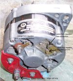
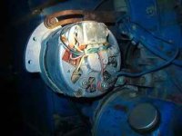
The new alternator has no identification on the terminals, and the I&T shop manual does not identify them, but an internet search seems to identify the terminals as: 12 o'clock, Field; 3 o'clock, AC Tap (?); 4 o'clock, GND; 7 o'clock, POS, (Battery); and 10 o'clock, REG.
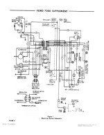
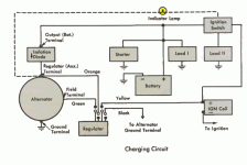
The Voltage regulator from fleabay also has no terminal markings, but the I&T shop service manual identifies them as: F A I G where F is Field (Green wire), A is (?)(Yellow wire) and goes to (?) terminal on alternator and to Alternator Warning lite, then from the light to "ON" on the key-switch. The I (Ignition??) terminal (Red wire) goes thru a fuse link to the "ON" terminal on the key-switch. The G terminal (Black wire) goes to ground.
So I dont have a problem with the Field, I, GND on the VR; or the Field, POS (Battery), GND on the Alternator.
My question is: does the A term on VR (yellow wire) go to the REG terminal on Alternator? And does it need to have a lamp or resistor(? ohms) in the wire to the key-switch?
The original alternator had a wire on the the (AC Tap (?)) but I dont know where it should connect or what is does, the I&T manual is no help there.
Click on the image to get full size rendition.
Thanks for any help....
So I tore out all the old wiring and have been rewiring what circuits I need. I have installed a new after-market temp gauge, Oil press gauge, and volt meter in an instrument panel I fabricated.
The new alternator has no identification on the terminals, and the I&T shop manual does not identify them, but an internet search seems to identify the terminals as: 12 o'clock, Field; 3 o'clock, AC Tap (?); 4 o'clock, GND; 7 o'clock, POS, (Battery); and 10 o'clock, REG.
The Voltage regulator from fleabay also has no terminal markings, but the I&T shop service manual identifies them as: F A I G where F is Field (Green wire), A is (?)(Yellow wire) and goes to (?) terminal on alternator and to Alternator Warning lite, then from the light to "ON" on the key-switch. The I (Ignition??) terminal (Red wire) goes thru a fuse link to the "ON" terminal on the key-switch. The G terminal (Black wire) goes to ground.
So I dont have a problem with the Field, I, GND on the VR; or the Field, POS (Battery), GND on the Alternator.
My question is: does the A term on VR (yellow wire) go to the REG terminal on Alternator? And does it need to have a lamp or resistor(? ohms) in the wire to the key-switch?
The original alternator had a wire on the the (AC Tap (?)) but I dont know where it should connect or what is does, the I&T manual is no help there.

Click on the image to get full size rendition.
Thanks for any help....


