downsizingnow48
Elite Member
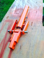
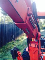
After 10 years I finally decided to install a hydraulic thumb on the B21. I was getting ready to make the thumb, and looked at Kubota parts diagrams to get some ideas. I learned that the BT751 backhoe and the BH77 backhoe use the same bucket pin. Meaning the buckets and also the mechanical thumb for the BH77 have to fit the BT751. The thumb cost $405 at the dealer, not a give-away, but not bad either considering steel prices and the work involved in making one from scratch.
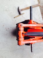
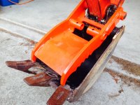
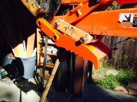
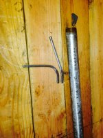
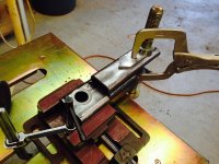
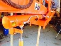
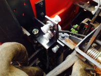
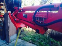
So today I did the easy part, installed the thumb. First picture shows the pin going in. I used a line-up pin with a tapered nose to get thumb, bucket, and stick in alignment, then chased that out with the hardened Kubota pin. It took about 3 minutes. The second picture shows the thumb installed.
It will be a while before I figure out exactly what the next step will be. Probably have to paint the old bucket, it didn't look that bad until I put the thumb on.
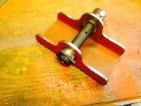
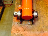
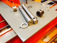
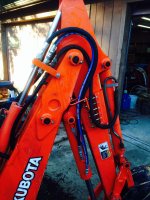
I am a bit concerned about the 25mm bucket/thumb pin, which is a Kubota factory item for the BH77, but looks a bit long and thin. The middle part of the pin is not supported (it is in a grease cavity). The bucket will work the same as ever, no reason to hold back on that, but I believe I might take it easy with the thumb. Pressing thumb and bucket hard together would have the effect of flexing the pin in the middle.
So today I did the easy part, installed the thumb. First picture shows the pin going in. I used a line-up pin with a tapered nose to get thumb, bucket, and stick in alignment, then chased that out with the hardened Kubota pin. It took about 3 minutes. The second picture shows the thumb installed.
It will be a while before I figure out exactly what the next step will be. Probably have to paint the old bucket, it didn't look that bad until I put the thumb on.
I am a bit concerned about the 25mm bucket/thumb pin, which is a Kubota factory item for the BH77, but looks a bit long and thin. The middle part of the pin is not supported (it is in a grease cavity). The bucket will work the same as ever, no reason to hold back on that, but I believe I might take it easy with the thumb. Pressing thumb and bucket hard together would have the effect of flexing the pin in the middle.