I would greatly appreciate help and comments from members in looking at this a conceptual model of Position and Draft Control. As will be painfully evident, I'm a retired pencil-pusher who has acquired a tractor and I know less than nothing about hydraulics (yes, it can be less than nothing because my head is full of negative, or false, information). I'm sure the attached diagram bears absolutely no relation to how things actually work, but is just a toy model that would help me to think about things.
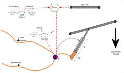
Please ignore the top of the diagram (draft control, sensor, and top link) for the moment.
So, there is some black-box valve/controller/magic at C that sends oil to the cylinder's piston and raises it to level B. It now continues to ensure that level B is maintained. This is straightforward as the oil has nowhere to go because C has locked all exit paths. The piston can, however, bounce above the oil level and it is only the implement's weight that holds it in place with a downward force. In some other tractors oil was actually maintained around the piston's rod to create a downward force as shown with the light grey color. However, modern tractors seldom do this.
The distance B is established by receiving a signal from the Position Control Lever. I have no idea whether this signal is hydraulic, mechanical or electrical. I don't think it really matters for the purpose of this toy model.
Returning now to the top of the diagram (and assuming Kubota uses top-link draft sensing), the black-box/magic Sensor shown senses the amount of strain that the tractor is being subjected to from the implement. If this strain exceeds a level controlled by the Draft Control lever (from Sensitive to Insensitive), the Sensor sends a signal to C that will inject more oil into the cylinder and thereby raise the implement just enough to reduce the strain on the tractor to an acceptable level. When the strain decreases to acceptable levels, the Sensor sends another signal to C, which will then allow the oil in the cylinder to exit just enough to return to level B (as defined by Position Control). B will/can never get below the level defined by the Position Control lever.
Is any of this even remotely accurate?
If so, the next mystery to me is the U (Up) setting on the Draft Control lever. It is beyond the most Sensitive setting so I'm guessing it simply means 途aise the lower links up now!? If true, I have no idea how this differs from raising with the Position Control lever. Does it respond faster? Or, by raising the 3pt this way, one doesn't lose the exact setting of Position Control?
Lastly, my manual says "place both Draft Control lever and Position Control lever in the F (float) position to make the lower links move freely along with the ground conditions". In terms of this toy model, does it mean "turn off strain sensing" and "reduce level B to a minimum level"?
Help please.
Attachments
Last edited: