The thing to keep in mind is that the limiting factor in the span tables is the amount of sag, so you don't come close to the actual breaking loads. There are two reasons that sag is the limiting factor: first, it is disconcerting to walk on a deck that sags, it feels like it might give way at any time, kind of like standing on a branch that bends a lot. Second, when a wooden structure moves the fasteners tend to loosen. If you have a bridge that moves around a lot you're putting a lot of strain on the nails and bolts.
Others have suggested building it so that the handrails form a truss. That is what I would do if I were building a footbridge any more complicated than a flat deck. A couple of years ago I volunteered on a National Park Service project to install a footbridge. They used a kit from this company:
Pedestrian and Trail Bridges - ETTechtonics
While the pieces were made out of fiberglass, they were all dimensioned the same as 2x lumber. The pieces were noticeably less rigid than wood, the joists were so floppy it was hard to keep them in place while they were bolted. The bridge we built had an unsupported span of 65 feet and a width of 4 feet. It had five 2x6-sized joists. The joists had to be supported by scaffolding until the truss was assembled but once it was all connected together the scaffolding was removed and the frame was rock solid. I guess my point is that a material far less stiff than wood can be engineered into a very stiff structure.
I'll try to give an idea of the construction. The bridge was basically two trusses connected by bracing underneath. Each truss consisted of two 2x6 joists on the bottom and two 2x6 handrails on the top. A fifth joist ran down the middle to keep the decking from being too bouncy. Each pair of joists/handrails was spaced 1.5 inches apart, the thickness of 2x lumber. The joists and rails were 12 or 16 feet long and there would be a piece of 2x6 as a splicing block between them where they joined. Every five feet there was a vertical post made out of 2x2. It ended flush with the top of the hand rails and extended past the joists by six inches. There was a diagonal brace from the top of each post to the bottom of the next one, also made out of 2x2, and bolted to the joists and handrails where it went between them. Below and perpendicular to the joists was a pair of 2x6's, which were bolted on either side of the piece of post extending down. These pieces were 8 feet and extended two feet out on either side of the bridge. At the ends of these two pieces a diagonal piece of 2x2 was bolted between them and slanted back to meet the post. Between those two pieces, in the middle of the bridge, was a vertical piece of 2x2 11 inches long. The fifth joist was bolted onto that. The two trusses were tied together by diagonal 2x2's from the bottom of one post to the bottom of the next.
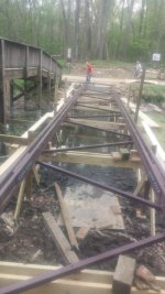
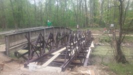
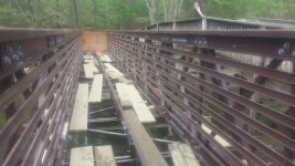
Here are some pictures that I hope make what I'm saying more clear:
Joists in place, you can see the splicing pieces and the cross braces, as well as the scaffolding:

Posts in place, along with diagonal bracing and the cross pieces. They did X-bracing but I think a single diagonal would be sufficient.

Center joist in, hand rails on, ready to take the scaffolding off. The NPS wanted pieces of 2x4 along the sides for safety and a piece of 2x6 along the top of the handrail, neither is necessary for strength.

If I were building a footbridge I would do something like this, but out of wood. I wouldn't go 65 feet with wood, but 15? Sure. I might upgrade some of the 2x2's to 2x4's, but mostly because the 2x2's you get at the store tend to be pretty lousy. It might be enough to make your own 2x2's by ripping graded lumber.
My recollection is that the cost of the kit for the 65-foot bridge was in the neighborhood of $30,000 or roughly $500 per foot. Which is really cheap for a 65-foot bridge and really expensive for a 14-foot one!


