YM135/YM186 Alternator wiring diagram

   / YM135/YM186 Alternator wiring diagram #1  

California

Super Star Member
Joined
Jan 22, 2004
Messages
14,745
Location
An hour north of San Francisco
Tractor
Yanmar YM240 Yanmar YM186D
Somebody posted the voltages that should appear on each terminal of the YM135/YM186 regulator (for the pancake alternator) and now I can't find this.

Any advice?
 
   / YM135/YM186 Alternator wiring diagram
  • Thread Starter
#2  
Followup - the YM186 Shop Manual has a chart of continuity/no connection between all the terminals on the regulator.

The regulator failed that test so I went to Gmiller's recent post and searched Ebay on all three numbers he shows for the regulator.

Same regulator is $20 for Kubota and Grasshopper, $25 if searched under 'Yanmar'. I bought a real Kubota OEM one for $20.

This followed a year of the dash light requiring higher and higher rpm to go out, until recently it has been on continuous. The alternator has continuity between its two wires so I assume its good.
 
   / YM135/YM186 Alternator wiring diagram #3  
This followed a year of the dash light requiring higher and higher rpm to go out, until recently it has been on continuous. The alternator has continuity between its two wires so I assume its good.

That's an odd thing. Would this also mean when new, it charged right away and the light went out. And now, higher RPMs to charge and the light to go out. hmmm Just thinking how the charging is happening from your input.
 
   / YM135/YM186 Alternator wiring diagram
  • Thread Starter
#4  
That's an odd thing. Would this also mean when new, it charged right away and the light went out. And now, higher RPMs to charge and the light to go out. hmmm Just thinking how the charging is happening from your input.
It's been flaky and uneven for a long time. The battery voltage tested good at my connection to feed the watering trailer pump so I just kept an eye on it. Recently it would stay bright red until 2000 rpm triggered it to go back to normal. Then past week, bright red all the time and 12.2 volts at that testing point. I traced for grounded wires or a bad connection, nothing found, so this $20 regulator is the next step.
 
   / YM135/YM186 Alternator wiring diagram #5  
Try the ‘ohiobruce’ post on the YM1100D for your readings on the various readings on given terminals.
I will confess, I did not reread all of that thread.
I believe that is the thread where rScotty went into great detail on both the voltage regulator and dyno.
Good luck with your repairs
 
   / YM135/YM186 Alternator wiring diagram
  • Thread Starter
#6  
Try the Ohiobruce post on the YM1100D for your readings on the various readings on given terminals.

I believe that is the thread where rScotty went into great detail on both the voltage regulator and dyno.
Good luck with your repairs
Thanks! That's the one.

YM1110D Won't Charge 7-12-2020.
 
   / YM135/YM186 Alternator wiring diagram
  • Thread Starter
#7  
Investigating a little farther - that YM1110 thread discussed the early alternator that has the diodes inside, controlled by an external 'Current Limiter' that sends a signal back to disengage some of the alternator windings when the battery is charged.

I just looked at the YM135/YM155 Service Manual that bmaverick posted on 11/30.
It has a through discussion of that internal-diode alternator.

I then looked at my slightly more recent (1980) YM186(D) Service Manual. It confirms that YM186 uses the later alternator that looks the same but doesn't contain diodes. The diodes are over in the firewall voltage regulator. This external regulator is the one that is often on Ebay for $20 and up.

This is good engineering on Yanmar's part. Replacing a $20 regulator is less than the $90 and up asked for a replacement alternator after the diodes - the weakest part in the charging system - fail.

Here's the troubleshooting page from YM186D Service Manual. No voltages are shown, just a go/no go chart for testing the regulator. Note the Probe +, Probe -. That's likely significant on a good regulator.


20201202_123235rYM186rRegulatorTest.jpg
 
   / YM135/YM186 Alternator wiring diagram #8  
How to determine whether or not your YM135 alternator has internal diodes (3-wire regulator "current limiter"), or has external diodes (4-wire regulator, or can be converted to 6-wire regulator):

Option 1: Inspect the back of the alternator. If you see two semi-circle plates full of connections and components ("soldered stuff"), your alternator has internal diodes.
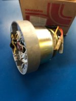
diodes.jpg
If the back of your alternator is bare aluminum with just two wires protruding, your alternator has external diodes.
nodiodes.jpg

Option 2: Use a multimeter to test for the presence of diodes in your alternator.
* Grab a digital multimeter with a diode testing function (the $7 one at Harbor Freight can do this)
* Disconnect the alternator leads from your tractor's wiring harness
* Connect the red lead of the multimeter to one lead of the alternator - then, connect the other multimeter lead to the other alternator lead
* Does the multimeter read zero, or some non-zero number?
* Swap the leads (red to black, black to red)
* Does the multimeter read zero, or some non-zero number?
* If the multimeter reads zero in one direction, but non-zero in the other direction - your alternator has internal diodes
* If the multimeter reads non-zero in both directions, your alternator has external diodes
* If the multimeter reads zero in both directions, either your diodes are bad or your alternator winding is bad

If you have an internal diode alternator that you want to use with an external diode regulator (4-wire or 6-wire setup), you can perform surgery on your alternator. Unscrew the diode plates from the back of the alternator. There should be two wires coming out of the alternator housing to the diode plates. There should be two leads coming from the diode plates to connect to the tractor's wiring harness. Simply bypass the diode plates - cut the diode plates out, and connect the leads to the tractor directly to the wires from the alternator.
 
   / YM135/YM186 Alternator wiring diagram #9  
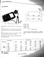
Here's the wiring diagrams for the 3-wire regulator and the 4-wire regulator setup on the YM135. I found this diagram years ago, but haven't seen it on the Internet since...
View attachment YM155 Wiring.pdf
 
   / YM135/YM186 Alternator wiring diagram
  • Thread Starter
#10  
Followup:

I installed the new regulator on the YM186D. Finally everything works as it should. No red light if the engine is running.

This is new. As long as I have owned it the charge light came on randomly as the engine slowed down but the battery voltage tested ok. Then recently the light was on all the time and the battery needed charging.

$20 for a 'take-off' regulator (obviously never mounted) from a Kubota dealer on ebay remedied everything.

I think I mentioned above that there was near-zero resistance between the alternator's two terminals so that wasn't the problem.

Thanks everybody for lots of good advice.
 
Last edited:

Tractor & Equipment Auctions

2019 ALLMAND BROS, INC. LIGHT TOWER (A45046)
2019 ALLMAND BROS...
132938 (A44391)
132938 (A44391)
2022 FORD F-250 (A45046)
2022 FORD F-250...
40ft 5 Dual Door Shipping Container (A44571)
40ft 5 Dual Door...
Scag Tiger Cat (A44502)
Scag Tiger Cat...
2012 Chevrolet Cruze Sedan (A42744)
2012 Chevrolet...
 
Top