Trails End
Gold Member
I'm in the process of installing the control linkeages for engaging
and disengaging the mid pto, which involves moving the spacer
shown in photo #2 from it's present location to the end where the
snap ring is. Apparently, when the dealer installed the single
rear hydraulic auxilliary kit, they opted to install the spacer
in it's present location, instead of where Bobcat intended it to
go. The Bobcat rear auxilliary kits (single or double) utilize the
same shaft, adding the spacer when only the single auxilliary
kit is installed. If the spacer had been installed just behind the
snap ring, as depicted in the Bobcat instructions, I wouldn't have
to remove the shaft at all. Photo #1 shows the area where the
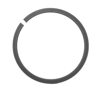
rear auxilliary control is. Photo #2 shows the spacer and the location
of the snap ring that must be removed to relocate the spacer.
The head of the shaft has to be against the bracket to make room
for the shaft extension for the mid pto control lever. Photo #3
shows the snap ring as viewed from the rear of the tractor (more
than an arm's length away).
I haven't been able to get a grip on the snap ring using the
snap ring pliers, since I can't see the hole locations of the
pin holes in the snap ring. I even tried using a mirror but
my hand-eye coordination just wasn't good enough to make
that work. By the way, the tractor is a Bobcat CT335 HST.:banghead::banghead:
Any tips or suggestions on how to approach this problem?
The only access I seem to have is from the top as shown
in Photo #1. The retaining ring pliers have the 90 degree
.047 dia. pins.


and disengaging the mid pto, which involves moving the spacer
shown in photo #2 from it's present location to the end where the
snap ring is. Apparently, when the dealer installed the single
rear hydraulic auxilliary kit, they opted to install the spacer
in it's present location, instead of where Bobcat intended it to
go. The Bobcat rear auxilliary kits (single or double) utilize the
same shaft, adding the spacer when only the single auxilliary
kit is installed. If the spacer had been installed just behind the
snap ring, as depicted in the Bobcat instructions, I wouldn't have
to remove the shaft at all. Photo #1 shows the area where the
rear auxilliary control is. Photo #2 shows the spacer and the location
of the snap ring that must be removed to relocate the spacer.
The head of the shaft has to be against the bracket to make room
for the shaft extension for the mid pto control lever. Photo #3
shows the snap ring as viewed from the rear of the tractor (more
than an arm's length away).
I haven't been able to get a grip on the snap ring using the
snap ring pliers, since I can't see the hole locations of the
pin holes in the snap ring. I even tried using a mirror but
my hand-eye coordination just wasn't good enough to make
that work. By the way, the tractor is a Bobcat CT335 HST.:banghead::banghead:
Any tips or suggestions on how to approach this problem?
The only access I seem to have is from the top as shown
in Photo #1. The retaining ring pliers have the 90 degree
.047 dia. pins.